Optical System Based On Terahertz Spectroscopy Technology
terahertz; optical system; fingerprint spectrum; substance identification
Abstract
The terahertz pulse signal has the characteristics of “fingerprint spectrum” in the frequency domain, which can be used for qualitative analysis of substances. A secondary aspheric TPX plano-convex lens was designed to improve the ability of lens to focus on the terahertz beams, with the help of optical analysis and optimization functions of Zemax software. The terahertz beam shaping optical system was designed by using the plano-convex lens, and the optical system was used in a terahertz time-domain spectroscopy system. The terahertz spectroscopy tests were performed on moxifloxacin hydrochloride and levofloxacin, and the absorption coefficient and refractive index curve in frequency domain were obtained after algorithm processing. The test results show that the refractive index of levofloxacin is higher than that of moxifloxacin hydrochloride in the range of 0.1 THz~3.5 THz band, but the change of the refractive index of moxifloxacin hydrochloride is more gentle than that of levofloxacin. The moxifloxacin hydrochloride has obvious absorption peaks at 1.03 THz, 1.92 THz, 2.58 THz and 2.84 THz, and the levofloxacin has obvious absorption peaks at 1.35THz, 1.96THz, 2.52THz, 2.73THz.
Introduction
Terahertz waves are a general term for electromagnetic waves between microwaves and infrared rays, their frequencies are between 0.1 THz and 10 THz, and their wavelengths are 0.03 mm~3 mm. The weak interaction forces (hydrogen bonds, Van Der Waals forces), framework vibrations, and dipole rotations within or between many macromolecules are just in the terahertz band, so different macromolecular materials will show specific characteristics in the terahertz band. Absorption and dispersion properties, the “fingerprint spectrum”, can be exploited for non-destructive identification of substances.
In general, broadband terahertz photoconductive antennas are used for terahertz spectroscopy tests.
Because it emits a terahertz beam with a certain divergence angle, it is necessary to design a corresponding optical lens to shape the terahertz beam, thereby increasing the terahertz energy density passing through the sample and increasing the accuracy of sample identification.
1 Design of terahertz beam shaping optical system
At present, the most widely used commercial terahertz photoconductive antenna is the 1 560 nm fiber-coupled antenna module of MenloSystems. In this paper, TERA15-TX-FC is used as the broadband terahertz source, and TERA15-RX-FC is used as the terahertz signal detector.
The terahertz beam divergence angle of TER A15-TX-FC is ±12.5°, and the electrode gap on the crystal is 100 μm; the terahertz beam acceptance angle of TERA15-RX-FC is ±12.5°, and the electrode gap on the crystal is 10 μm.
Therefore, the terahertz source and detector can be regarded as a point source and a point detector, whose divergence angle and acceptance angle are both ±12.5°, and a transmissive optical system is used to shape the terahertz beam.
The photoconductive terahertz source used in this paper is a broadband source, and the spectral width used in spectral detection is usually 0.1 THz ~ 3.5 THz, and most of the energy is concentrated between 0.1 THz ~ 1.0 THz.
Within this wide spectral range, it is unavoidable that the focused spot size difference caused by dispersion and diffraction limit effects is large, as long as it is ensured that after passing through the sample, the broad-spectrum signal carrying the sample information can be received by the terahertz detector.
Considering the sample size and the accuracy of spectral detection, the design index of the sample spot is set to be ≤1 mm.
1.1 Single lens design
In this paper, four identical plano-convex lenses are used to form a terahertz beam shaping optical system, which can effectively reduce the device cost of the optical system. At the same time, in order to reduce aberrations, the focused light is located on the plane side of the optical system.
Polymethylpentene (TPX), the lightest known polymer material, is transparent in the UV, visible, and terahertz bands, with a refractive index of about 1.46, which is relatively wavelength-independent.
Therefore, TPX is generally used as a material for the production of terahertz lenses. TPX lenses can be molded by mold casting and have good surface quality stability.
In order to increase the terahertz energy density focused on the sample, an aspheric coefficient is introduced into the plano-convex lens to further enhance the focusing ability of the lens. The quadratic aspheric equation is expressed as
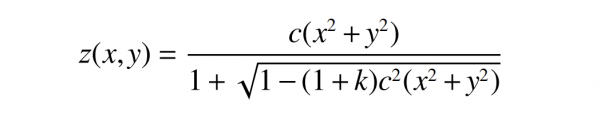
where:
c is the radius of curvature;
k is the conic surface constant.
When k=0, the above formula is a spherical equation with the center of the sphere coincident with the origin of the coordinates.
Since the main function of the plano-convex lens in the terahertz optical path is to collimate and focus the terahertz beam, the single-lens design takes the beam parallel to the optical axis as the incident light, and adopts the single-objective optimization method. The coefficient k and the back intercept l are used as optimization variables, and the minimum spot size is used as the optimization target.
Considering the terahertz source beam parameters, optical path layout, lens installation and other factors, the initial structure of the designed plano-convex lens is shown in Figure 1, and the initial focal length l is 50 mm.
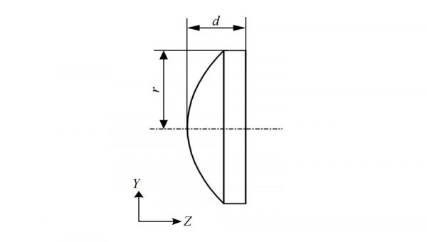
Fig. 1 Structure parameters of plano-convex lens
The TPX material was established in Zemax, and three typical bands of 3 000 μm (0.1 THz), 300 μm (1.0 THz), and 85.7 μm (3.5 THz) were selected. The focusing spot size of the single lens in these three bands is shown in Figure 2.
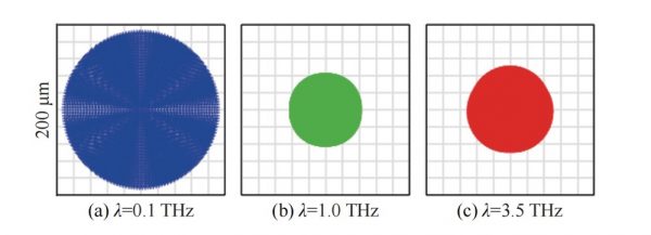
Fig. 2 Size of focused spot on single lens
Fig. 2(a) is the spot size of 3 000 μm wavelength (0.1 THz) with a diameter of 0.18 mm; Fig. 2(b) is the spot size of 300 μm wavelength (1.0 THz) with a diameter of 0.08 mm; Fig. 2(c) is a spot size of 85.7 μm wavelength (3.5 THz) with a diameter of 0.10 mm.
It can be seen from Figure 2 that the area around 0.1 THz ~ 1.0 THz is also the largest range of broadband terahertz energy, and the focus spot size is directly used as the optimization target. Through the combination of local optimization and Hammer Optimization, the best set of The lens parameters are shown in Table 1.
Table 1 Optimization parameters of plano-convex lens
| wdt_ID | Parameter | Before optimization | After optimization |
|---|---|---|---|
| 1 | r/mm | 17.55 | 17.55 |
| 2 | d/mm | 9.5 | 9.5 |
| 3 | c/mm | 28 | 27.315 |
| 4 | k | 0 | -0.574 |
| 5 | l/mm | 50 | 52.641 |
1.2 Optical system design
On the basis of four identical plano-convex lenses, and the sample to be tested as the center, a terahertz beam shaping optical system with a symmetrical structure is designed, as shown in Figure 3.
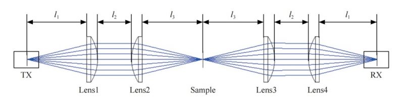
Fig. 3 Terahertz beam shaping optical system
In Figure 3, TX is the terahertz source, RX is the terahertz detector, Lens1 and Lens3 are collimating lenses, Lens2 and Lens4 are focusing lenses; after optimization, l1=52.641 mm, l2=30 mm, l3=53.598 mm.
The conical diverging beam emitted by the terahertz point source is collimated by the first plano-convex lens, and then focused on the sample by the second plano-convex lens. The terahertz beam that passes through the sample and carries the sample information is collimated by the third plano-convex lens, and then The fourth plano-convex lens focuses on the crystal of the terahertz detector.
The above optical system was established in Zemax, with l1, l2, l3 as the optimization variables, and the minimum spot size at the sample as the optimization goal, and the final optical system structure was obtained (see Figure 3).
The size of the spot imaged by the optimized terahertz beam shaping optics on the sample surface is shown in Figure 4.
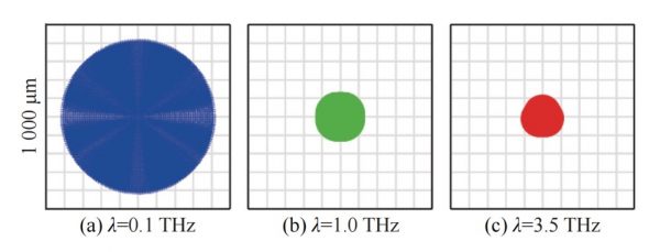
Fig. 4 Size of focused spot on sample surface
Fig. 4(a) is the spot size of 3 000 μm wavelength (0.1 THz) with a diameter of 0.81 mm; Fig. 4(b) is the spot size of 300 μm wavelength (1.0 THz) with a diameter of 0.23 mm; Fig. 4(c) is a spot size of 85.7 μm wavelength (3.5 THz) with a diameter of 0.21 mm.
It can be seen from Figure 4 that the maximum spot diameter on the sample surface is 0.81 mm, which meets the design goal of ≤1 mm.
2 Terahertz spectral testing and data processing
The terahertz optical lens is installed on the optical guide rail and connected to the terahertz time-domain spectroscopy system at the same time, and the detected terahertz signal is the strongest by fine-tuning the axial distance of each component. The experimental setup for spectral testing is shown in Figure 5.
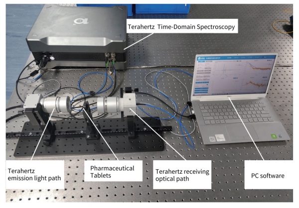
Fig. 5 Terahertz spectrum test
Moxifloxacin hydrochloride and levofloxacin were selected as test samples, and solid pressed tablets with a thickness of 1.25 mm were made, and the terahertz time-domain signals of non-passing samples and passing samples were collected respectively.
Taking the terahertz signal of the sample that did not pass as the reference signal, as shown in Fig. 6(a) and Fig. 6(b), the time window is 83 ps~140 ps, and the step is 0.05 ps.
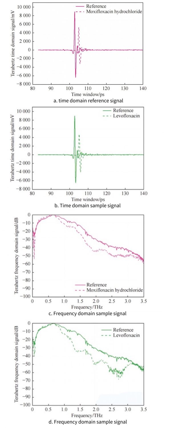
Fig. 6 Terahertz time-domain and frequency-domain signals
Fourier transform is performed on them respectively to obtain the reference signal and frequency domain sample signal of moxifloxacin hydrochloride and levofloxacin in the terahertz frequency domain, as shown in Figure 6(c) and Figure 6(d), the frequency display range is 0 ~3.5 THz.
In the case where only the main terahertz peak signal is extracted, the reflected echo signal is not considered, and the terahertz signal is incident on the sample vertically, the complex transmission function of the terahertz signal passing through the sample can be expressed as
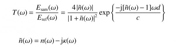
where
Esam(ω) is the terahertz signal passing through the sample;
Eref(ω) is the reference signal;
ñ(ω) is the complex refractive index of the sample;
n(ω) is the actual refractive index of the sample;
k(ω) is the extinction coefficient of the sample;
d is the thickness of the sample;
c is the speed of light in vacuum, is 3×10⁸ m/s.
The complex transmission function is expressed in the form of a modulus and an argument , that is
![]()
Among
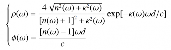
The refractive index n(ω), extinction coefficient κ(ω) and absorption coefficient α(ω) of the sample can be obtained from the above formula:
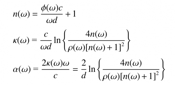
According to the above formula, the optical parameters of moxifloxacin hydrochloride and levofloxacin were calculated to obtain their respective refractive index and absorption coefficient, as shown in Figure 7.
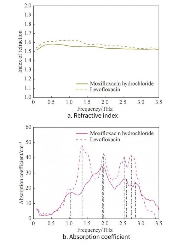
Fig. 7 Frequency-domain curves about refractive index and absorption coefficient of moxifloxacin hydrochloride and levofloxacin
Figure 7(a) shows the refractive index curves of moxifloxacin hydrochloride and levofloxacin. It can be seen that the refractive index of levofloxacin is in the band of 0.1 THz to 3.5 THz, which is higher than that of moxifloxacin hydrochloride.
But the change of the refractive index of moxifloxacin hydrochloride is more gentle.
Figure 7(b) shows the absorption coefficient curves of moxifloxacin hydrochloride and levofloxacin. It can be seen that moxifloxacin hydrochloride has obvious absorption peaks at 1.03 THz, 1.92 THz, 2.58 THz, and 2.84 THz, and levofloxacin has obvious absorption peaks at 1.35 THz, 1.96 THz. There are obvious absorption peaks at THz, 2.52 THz, and 2.73 THz.
3 Conclusion
Because the weak interactions (such as hydrogen bonds and van der Waals forces), skeleton vibration and dipole rotation in macromolecular substances are just in the terahertz spectrum range.
Therefore, macroscopically, such substances exhibit unique fingerprint spectrum characteristics in the terahertz band.
In this paper, a transmissive terahertz beam shaping optical system is designed based on the broadband terahertz source and detector of MenloSystems. Refractive index and absorption properties of moxifloxacin hydrochloride and levofloxacin in the terahertz band.
The test results show that the two have obvious fingerprint spectrum characteristics in the terahertz band, and can be effectively distinguished.
The designed terahertz beam shaping optical system provides technical support for the subsequent application of terahertz technology in the fields of non-destructive testing and material identification.