Optical design of THz image surface scanning with an off axis parabolic mirror
THz; off axis parabolic mirror; image surface scanning; optical design
Abstract
In order to improve the THz imaging speed, an image surface scanning THz fast imaging system was designed. It was a single pixel imaging system basing on the reflection type. The system collected THz by an off axis parabolic mirror which was used to realize the imaging of large caliber, high transmittance, high quality imaging. The optical parameters of system were that F/# was 2.93, the aperture diameter was 120 mm, the field angle was ±1°, the focus length was 293.45 mm, the size of imaging window was 64 mm×64 mm, the diameter of circular hole was 2 mm, the imaging speed of 16×16 pixels was 0.1 min, the imaging speed of 32×32 pixels was 0.47 min, the imaging speed of 64×64 pixels was 1.7 min, and the spatial resolution was 10 mm. The system combined with compressed sensing theory and image surface scanning theory realized the fast imaging property.
A rotation plate with holes was inserted at image surface position, which scanned the THz intensity. Then a light cone was employed to collect energy to the Golay detector. The device output image by a special situation of compressed sensing theory that the sample number equaled to the image pixels. Sequentially, the regular least squares algorithm was used to reconstruct intensity distribution. The system has the property of high imaging speed and resolution, low costs, and small structure.
0 Introduction
Terahertz waves are electromagnetic waves with frequencies in the range of 0.1 to 10 THz, which are located in the middle of the infrared band and the microwave band. Terahertz electromagnetic waves, also known as T-rays, fall into the category of far-infrared and submillimeter waves.
In the past 20 years, terahertz has undergone profound changes, and as new materials provide high-power emission sources, terahertz has been used in more and more research fields. Terahertz signals have strong penetrating power. Terahertz imaging technology is widely used in material detection, non-destructive testing, security scanning and medical fields. Terahertz imaging technology mainly includes time-domain spectral imaging, tomography, and holographic imaging. and continuous wave imaging, etc.
The time-domain spectral imaging system extracts data reflecting sample information from the time-domain waveform of the electric field for imaging. Time-domain imaging has high working bandwidth and high imaging resolution, but the scanning time is long. Compared with time-domain spectral imaging, continuous terahertz imaging only detects the intensity information of electromagnetic waves after passing through the sample or reflected by the sample, and does not have the ability to provide phase information. information capacity.
However, the continuous terahertz imaging system has the characteristics of high radiation power, simple system, low price, fast imaging speed, and convenient use. For scanning objects that are relatively large and only need to detect defects or transmission properties, continuous terahertz imaging has obvious advantages.
The THz imaging technology used before is mainly point-by-point scanning imaging, but point-by-point scanning imaging will reduce the sampling speed. At present, it takes about 20 minutes to obtain an image of 100 × 100 pixels in the current mechanical point-by-point scanning method. Disadvantages of high degree and high cost.
Therefore, finding more and better THz imaging methods is also one of the focuses of current THz imaging research. The off-axis parabolic mirror THz imaging technology based on image plane scanning is a new imaging technology developed by applying the compressed sensing theory of signal compression to THz imaging.
This method can avoid the traditional mechanical point-by-point scanning, abandon the expensive and complex terahertz array detectors, and combine the advantages of high reflectivity and aspheric aberration of off-axis parabolic mirrors to achieve real high-quality fast terahertz. imaging method.
1 Principle
1.1 Scanning principle
The traditional signal acquisition and processing process mainly includes four parts: sampling, compression, transmission and decompression, which must satisfy Shannon’s theorem, that is, the sampling frequency cannot be lower than 2 times of the analog signal frequency. In the traditional signal transmission compression process, the signal is first transformed, and then a small number of coefficients with large absolute values are compressed and encoded, and zero or close to zero coefficients are discarded. This data compression discards most of the previously collected data. Affects the final result or image, but captures a lot of wasteful information that consumes time and resources.
If the signal itself is compressible, the compressed data of the signal can be directly obtained by using compressed sensing theory, thereby saving time and reducing unnecessary data acquisition process. The core idea is that the compressible signal is sparse in a certain transform domain.
In this way, the high-dimensional signal obtained from the transformation of the transformation basis and the uncorrelated observation matrix can be projected onto a low-dimensional space, and then the original signal can be obtained by optimizing the solution. This method breaks through the Shannon sampling theorem.
The measurement process of the compressed sensing theory is linear, assuming that P is a two-dimensional original signal of length N, and the measured value Y is the linear projection of the original signal under the measurement matrix Φ. The projection formula is:

where: M represents the number of measurements, so Y is a two-dimensional signal of length M×N, When M=N, ΦM×N is a square matrix, and the equation is a well-posed equation, which is easy to solve. Figure 1 shows the calculation process of the 2×2 pixel image according to the above formula.
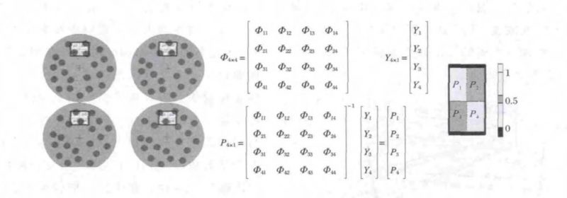
Fig.1 Measurement matrix equation
1.2 Selection of imaging methods
THz optical systems need to be designed according to the application. At present, the structural forms of optical systems are mainly divided into refraction type, catadioptric type and reflection type. The THz optical system design should meet the following requirements:
(1) Small size, easy to install and debug the whole machine;
(2) Relative aperture as large as possible;
(3) Field of view that meets the requirements;
(4) Minimum radiant energy loss in the selected band;
(5) Adapt to different environments, and have reliable and stable optical performance, etc.
Refraction (transmission) THz optical system has the characteristics of large field of view, low F number, mature processing and adjustment technology, various aberrations can be eliminated, light and compact structure, good transmission and stable performance. In the two-dimensional imaging optical system, photoelectric crystals are generally used for detection, and the object distance of the optical system is much larger than the focal length of the lens.
Its imaging resolution Δ=1.22λDt f/(DsD); when the size of the detection crystal, the diameter of the lens and the detection wavelength are determined, the harmonic diffraction/refractive zoom optical system as shown in Fig. 2 can be designed to obtain an image with a certain resolution. However, this design is limited by material properties, and the loss of light energy is relatively large. It is difficult to achieve a design with a large aperture and a long focal length, and it is difficult to increase the relative aperture and the length of the compression structure.
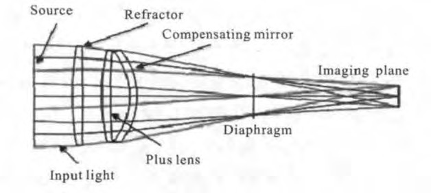
Fig.2 Diagram of THz refraction zoom optical system
The off-axis three-reflection THz optical system has the advantages of easy access to large-diameter reflective materials, no chromatic aberration and better correction of spherical aberration and coma aberration, small light energy loss, wide operating band, and short total system length. As shown in Figure 3, Figure 3(a) is a schematic diagram of an off-axis three-mirror optical system; Figure 3(b) is a diagram of a coaxial three-mirror optical system.
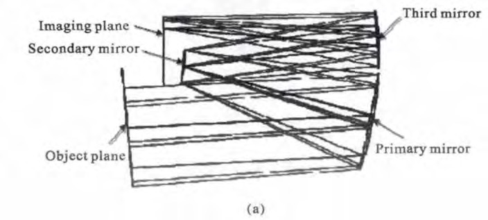
Fig.3 Diagrams of off-axis three-mirror optical system and on-axis three-mirror anastigmatic system (a)
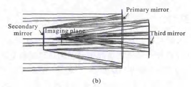
Fig.3 Diagrams of off-axis three-mirror optical system and on-axis three-mirror anastigmatic system (b)
Using ZEMAX optical imaging design software, the initial structure calculation is realized by writing simple ZPL macros and the diaphragm and field of view are off-axis, and then the ideal optical system is designed through the optimization calculation. However, its F-number is relatively large, the center blocks light, the complexity of the optical-mechanical structure increases, the processing and assembling are difficult, the stray light is not easy to control, and the production cost is high, and it is difficult to meet the requirements of large-field and large-aperture imaging.
Since materials with good transmission properties in the terahertz band are very scarce at present, lenses suitable for the terahertz band are difficult to obtain, and lenses suitable for terahertz materials are not suitable for visible light, and the system is very difficult to tune.
Therefore, refracting and catadioptric systems are difficult to achieve in the terahertz band. Due to the complex design of the off-axis three-mirror system, the system F number is low, and it is difficult to assemble and adjust. The off-axis parabolic mirror system is less affected by the material limitation, the reflective material is easier to obtain than the refracting material, the energy attenuation is small, and there is no chromatic aberration at all, and it can be used. Eliminate the influence of spherical aberration, wide applicable band, high system transmittance, convenient for lightweight design.
However, the currently available off-axis parabolic mirrors are mainly used for collimating terahertz waves, and their apertures are small, so they are not suitable for long-distance imaging. Therefore, ZEMAX optical design software is used to design the optical system of the large-diameter and high-reflectivity off-axis parabolic mirror to ensure the quality of terahertz imaging.
1.3 Imaging principle
The working principle of the imaging device is:
The terahertz wave reflected from the target contained in the observed instantaneous field of view is irradiated by the active terahertz radiation source, and is reflected and imaged on the focal plane by the off-axis parabolic mirror. The metallic light cone collects all the energy focused on the imaging window, sampled with a terahertz single-pixel detector. In this way, the data obtained by the detector is the result data of the inner product of the corresponding pattern of the instantaneous disk on the imaging window and the image intensity of the image plane.
If the disk rotates at a constant speed according to the set speed, the image surface light and different patterns of the imaging window are multiplied within one cycle of rotation. At the same time, the inner product result of each time is recorded, that is, the inner product data array is obtained.
The pattern on the imaging window is fixed at each moment when the disk rotates once, that is, the measurement matrix is also fixed. And through the pre-experiment calibration, it can be obtained that the whole measurement process belongs to linear measurement, and finally through the product of the inverse matrix of the measurement matrix and the inner product array, the energy intensity distribution of the image surface is inverted, and the original signal, that is, the target image, is obtained.
Before using the device, the disk matrix needs to be measured, and the visible light integrating sphere is used to provide uniform light source illumination, so that the radiance or illuminance illuminated on the disk imaging window is almost uniform. Then use the visible light band detector with the same sampling frequency as the GOLAY detector to perform the same frequency sampling and the same frequency and the same initial position rotation to measure the single pixel intensity image within a period of time to save the data.
Due to the high uniformity of the brightness or illuminance of the image plane, it can be considered that the energy reaching the imaging window is uniform, the measured intensity is normalized, and then the relative measurement method is used to measure the energy intensity value at the position of the imaging window, according to the formula (projection formula in above) can obtain the measurement matrix ΦM×N of the circular hole in the frequency and the test time range. When ΦM×N is determined, the matrix can be used to calculate the energy intensity of the imaging window position in the actual measurement.
Figure 4 is a schematic diagram of the system image scanning disk designed by CAD. The size of the imaging window is 64 × 64 mm, the size of the circular hole is 2 mm, and the rotation speed corresponds to the number of pixels of the final output image.
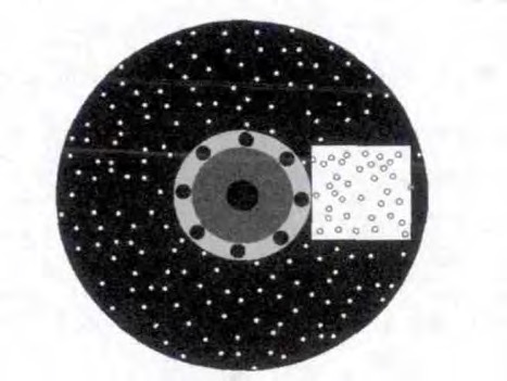
Fig.4 Schematic diagram of plate with holes
2 Device imaging modes
Due to the low terahertz radiation energy in nature, an external active radiation light source is required to perform terahertz active illumination on the target object. The image plane scanning terahertz fast imaging equipment consists of an active radiation illumination system, a reflection imaging system, an image plane scanning system, an energy collection system and a detection system, as shown in Figure 5.
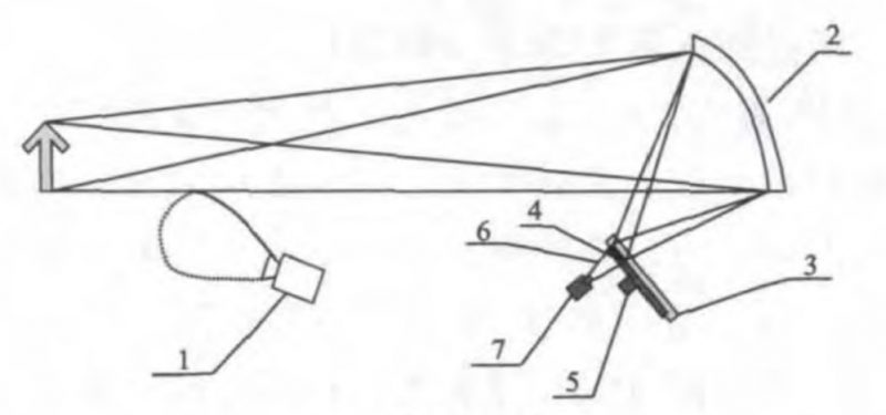
Fig.5 System structure
The active radiation system consists of a CW continuous terahertz radiation source 1; the reflective imaging system consists of a self-designed gold-coated off-axis parabolic mirror 2; the image plane scanning system is composed of a porous disc 3, a fixed imaging window 4, and a rotary motor 5; the energy collection system is composed of a terahertz high reflectivity metal light cone 6 ; the detection system is composed of a terahertz single-pixel GOLAY detector 7 .
The CW continuous terahertz radiation source provides tens of milliwatts of high-power radiation to the target object; the gold-coated off-axis parabolic mirror can achieve large-diameter, high-reflectivity, and high-quality imaging. Its clear aperture is 120 mm, and the system at the image plane is designed. The diameter of the diffused spot is much smaller than the diameter of the system Airy disk, and the imaging quality reaches the diffraction limit.
The image plane scanning system is composed of a fixed imaging window and a rotating porous disk to achieve dynamic scanning at the image plane, so that the pattern of the porous disk in the imaging window and the instantaneous image plane energy intensity at each instant have an inner product effect, and the motor drives the dynamic scanning of the image plane. The disc rotates, and a limited number of sampled intensities and disc patterns are internally integrated within a cycle period. The number of inner products is equal to the number of pixels of the final image to be obtained. When the disc design is completed and the rotation period is determined, then in one cycle The disk pattern matrix displayed on the inner imaging window is a definite value, corresponding to the number of pixels in the result image, a definite measurement matrix ΦM ×N is obtained.
The detection system uses a terahertz GOLAY detector with a typical response time of 25 ms and a sampling frequency of up to 40 Hz. A certain number of samples are collected in one cycle, and the measured data is YM×N. The principle of image processing is based on the linear measurement relationship YM×N = ΦM×N PN×N, the equation system is established by the measurement matrix and the measurement data, and the regularized least squares method is used.
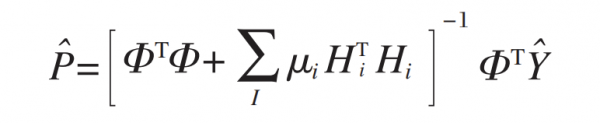
Fast and accurate solution, get the original signal XN×N to get the target image, According to the above principle analysis and calculation of sampling time, when the size of the imaging window is 64 × 64 mm, According to the typical detector sampling frequency of 40 Hz, it can be calculated that: when the number of reconstructed pixels is 256, the sampling time is 0.1 min; when the number of reconstructed pixels is 1024, the sampling time is 0.42 min; when the number of reconstructed pixels is 4 096, the sampling time is 1.7 min.
3 Design Examples
In the design of the optical system, the virtual plane in front of the mirror is used as the global coordinate reference plane. Based on the design of the coaxial reflective optical system, a complete system design is obtained by adding off-axis eccentricity and tilt optimization. First, on the basis of the coaxial system, according to geometric optics and aberration theory, the focal length of the coaxial system is 1/2 of the radius of curvature of the mirror, that is, f=r/2, and the initial structure of the optical system including the mirror is calculated. The curvature of the vertex, the conic coefficient, the interval and other parameters, and then set the diameter of the entrance pupil of the system, the radius of curvature of the mirror and the thickness of the interval, the size of the image surface is set to be equal to the width of the imaging window, and the eccentricity of the system is determined by the formula in below calculate:
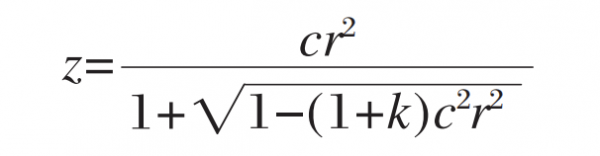
where:
c is the radius of curvature of the vertex;
r is the radial coordinate unit of the lens;
k is the aspheric coefficient constant.
When k<-1, it is a hyperboloid, when k=-1, it is a paraboloid, when -1<k<0, it is an ellipsoid, and when k=0, it is a sphere.
So take k=-1. Set the initial off-axis eccentricity value of the mirror according to formula above, and set the eccentricity and tilt of the image surface to correspond to the mirror, so as to ensure the imaging quality at the image surface, and then offset the mirror off-axis. The final design result is obtained by setting the threshold of the Merit Function optimization function: the eccentricity DY represents the y-direction eccentricity relative to the reference surface; the inclination angle TX represents the rotation angle relative to the reference surface around the x-axis, clockwise is positive, and counterclockwise is negative; the aspheric coefficient Conic/4th represents the conic coefficient of the lens surface/4th degree aspheric coefficient. The optical design diagram of the off-axis parabolic mirror is shown in Figure 6, and the structural parameters of the optical design system are shown in Table 1.
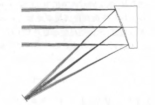
Fig.6 Optical design diagram of parabolic mirror
Tab.1 Parameter of optical design
| wdt_ID | Surface | Radius/mm | Interval/mm | Offset DY/mm | Tilt angle TX/(°) | Material | Aspheric coefficient |
|---|---|---|---|---|---|---|---|
| 1 | Object surface | ∞ | 20000 | 0 | 0 | Air | 0/0 |
| 2 | Mirror | -586.905 | -297.780 | 200 | 0 | Mirror | -1 |
| 3 | Imaging plane | ∞ | 0 | -203.344 | -37.636 | Air | 0 |
Figure 7 shows the untilted scatter speckle of the system at five different object-side FOV positions. It can be seen that the untilted image plane has obvious coma aberration.
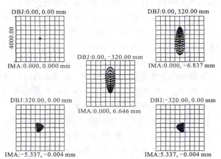
Fig.7 Spot diagram of optical system without tilt
Figure 8 shows the diffused spot on the image surface after adding the corresponding parabolic mirror inclination. It can be seen that the diffused image of the system is better, much smaller than the size of the Airy disk, and the system has a diffraction effect, which is caused by the long terahertz wavelength. Yes, at this time, it is necessary to analyze the imaging effect from the perspective of physical optics. In order to more accurately judge the imaging quality of the final image plane, it is also necessary to observe the modulation transfer function (MTF) curve of the system, the diffraction energy concentration curve and the system point spread function curve. When the pixel size of the imaging window is set to 1 mm, the space is divided into Resolution is 1 cm.
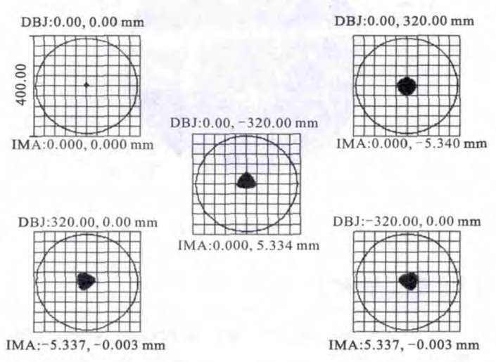
Fig.8 Spot diagram of optical system
MTF reflects the transmission ability of the optical system to different spatial frequency components. For an imaging system, the larger the MTF, the better the imaging quality. It can be seen that the MTF of the optical system basically reaches the diffraction limit, and the transfer function of each field of view at the cut-off frequency. All values are above 0.5, and the image quality is good. Figure 9 shows the MTF curves of the designed system at 5 different object plane sizes—0, x: ±320 mm, y: 3 ±20 mm, and the imaging quality is close to the diffraction limit.
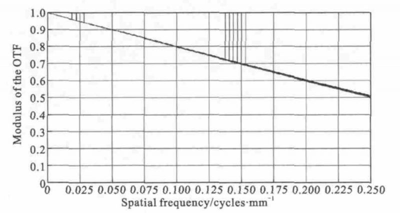
Fig.9 MTF of optical system
The diffraction energy concentration curve shows the energy distribution on the image surface. Its abscissa represents the radius of the circle centered on the chief ray, and the ordinate represents the percentage of the energy contained in the circle to the total energy, as can be seen from Figure 10. : The detector can receive nearly 90% of the energy within 5 mm of the bell mouth, and the energy concentration basically reaches the diffraction limit, which meets the design requirements.
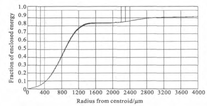
Fig.10 Diffraction energy concentration curve of optical system
The point spread function can calculate the intensity distribution of the diffraction image formed by an optical system emitted by a certain point light source on the object side. It can be seen from Figure 11 that the main lobe has a sufficiently high peak relative to the side lobe and the main lobe is distributed in the detector. The system receives most of the energy within the size of the bell mouth.
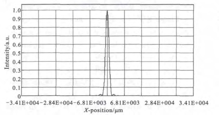
Fig.11 PSF curve of optical system
It can be seen from the analysis of the image quality of the above designed optical system that the system has good imaging quality and can meet the design requirements of terahertz band imaging.
4 Conclusion
The newly designed off-axis parabolic mirror surface scanning terahertz imaging system using ZEMAX software can transmit images quickly. The F number of the reflection imaging system is 2.93, the clear aperture is 100mm, the field of view is ±1°, the focal length is 293.45 mm, and the imaging window is 293.45 mm. The size is designed to be 64 × 64 mm.
When reconstructing an image of 64 × 64 pixels, the spatial resolution is 1 cm. The newly designed rotating porous disc is used for compression measurement. The traditional point-by-point scanning imaging is abandoned, and the number of pixels is directly determined. Measure the number of times, and then obtain the target image through the regularized normalization reconstruction algorithm. The system has low difficulty, compact structure, small size, light weight, convenient use, low consumption and energy consumption, stable performance, long life, can be integrated, and can be batched. Production, low cost, etc., easy to achieve modularization, real-time rapid analysis, and field application value