Spot characteristics of laser beam after focusing by off-axis parabolic mirror
parabolic mirror, off-axis, angular misalignment, divergence angle
Abstract
Starting from geometric optics and physical optics, the influence of the angular misalignment of the optical axis and the divergence angle of the incident light on the focused spot is analyzed when the parabolic mirror is applied to the focusing optical path of the laser beam in a way of 90° off-axis. When the mode Gaussian light is collimated and incident, since the parabolic mirror has no spherical aberration, the peak light intensity of the focal spot will be proportional to the square of the diameter of the incident light.
The ray tracing method proves that the angle misalignment leads to a pair of focal lines that are perpendicular to each other. Diffractive optics know that the incident Gaussian light will be transformed into an elliptical Gaussian light, which reduces the peak light intensity at the focal plane. The parabolic mirror is very sensitive to the misalignment of the incident angle, and the error of the order of m rad is enough to make the focal plane misalignment. The peak light intensity of the focal plane is reduced by about half. Moreover, the increase in the diameter of the incident beam will greatly reduce the tolerance to angular misalignment, making the peak light intensity at the focal plane more sensitive to misalignment. At the same time, it also proves the existence of divergence angle It will cause coma aberration and reduce its peak light intensity.
1 Introduction
For a parabolic mirror, ideally, when the incident light is strictly parallel to the optical axis, the reflected light is focused at point F.
Its spherical aberration is zero, which reduces light disturbance, and its durability to high-intensity lasers has recently been widely used in the focusing and deflection of laser beams. However, it is extremely sensitive to the misalignment of the optical axis, and the astigmatism caused by the misalignment greatly reduces the focused light intensity. Therefore, it is necessary to precisely adjust the optical axis.
Here, a parabolic mirror with a focal length f of 200 mm is used, and the diameter of the incident beam is adjusted by the beam expander technique of a series biconvex lens, and the divergence angle of the incident light can be adjusted, so that the effects of the misalignment angle and the divergence angle of the incident light can be separately studied. First, the effect of the divergence angle of the incident light is minimized, the effect of the misalignment angle is studied, and finally the effect of the divergence angle is discussed.
2 Influence of misalignment declination
2.1 Ray tracing method
Select a wavefront ABC of the incident light, move the coordinate origin to point B, and obtain a new coordinate system B x’y’z’. Assume that the incident light is a uniform circular beam. The wavefront ABC is represented by a hexagonal ring array, as shown in Figure 1 . Take any point in the figure, the corresponding incident ray equation can be obtained from the known declination value, and the paraboloid equation
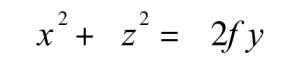
formula 1
The joint solution (discarding the large false solution), the intersection of the incident light and the parabola ( x0 , y0 , z0 ) can be obtained. From the formula 1, the normal of the paraboloid at the intersection can be obtained as
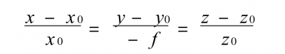
formula 2
Using the angle relationship between the incident ray, the reflected line and the normal line, the direction angles T0, U0, V0 of the reflected line can be obtained. The reflected line is
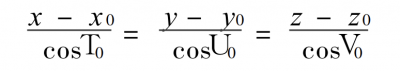
formula 3
From formula 3, the position of the corresponding light spot in any z plane can be obtained, and by taking all the points in Figure 1, and taking the light intensity at the corresponding point as the weight, the shape of the light spot and the approximate light intensity distribution in any z plane can be obtained.
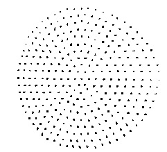
Fig . 1 Incident laser lattice
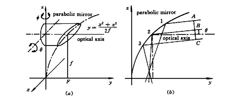
Fig . 2 Schematic diagram o f 90° off-axis parabolic mirror (a ) coordinates; (b ) laser beam focused by a parabolic mirror at misalign men t angle of θ
2.2 Physical Analysis
Figure 3 (a) is the light spot diagram when a uniform circular beam with a diameter of 40 mm is incident at an angle of θ = 2 mrad (the origin of coordinates in Figures 3 and 4 is on the optical axis passing through point F, Figures 12 and 13 the same as).
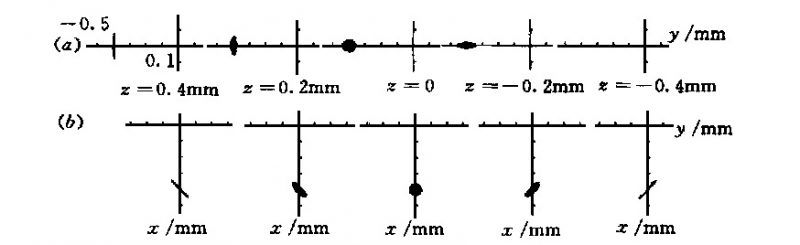
Fig. 3 Spot diagram (a ) θ= 2 mrad (O= 0); (b ) O= 2 mrad (θ= 0)
Due to the existence of oblique astigmatism, a focal line is generated, one of which is between the focal plane and the mirror surface, parallel to the x-axis, but with a slight radian, which is the sagittal focal line; the other is outside the focal plane and parallel to the y-axis. The axis, almost entirely in the yz plane, is the meridian focal line.
There is an approximate circular light spot between the two focal lines, which is the minimum circle of confusion.
The y-axis of this kind of circular light spot is symmetrical on both sides, and gradually changes from the short diameter of the near F point to the long diameter of the far F point. It should be pointed out that these two focal lines have a certain line width and are not ideal focal lines. This is caused by coma aberration, which also leads to the asymmetry of the minimum circle of confusion. The influence of coma aberration here It is far smaller than the influence of oblique astigmatism, so the following is simplified processing, and only the influence of the latter is considered.
Figure 3(b) is the light spot diagram when the declination angle is O = 2 mrad.
There is also a focal line, the difference is that the angle between the focal line and the x and y axes is 45°, and the two focal lines are perpendicular to each other, and both have a slight radian; the circle-like light spot between the two focal lines has a long diameter near the F point, and a short diameter at the far F point, which is exactly the opposite of the θ angle.
Considering the influence of diffraction, the light distribution at the actual focal line should be a flat ellipse, and the diameter of the approximate circular light spot on the focal plane should also be larger than the calculated value. And the smaller the calculated value, the greater the effect of diffraction. We are more concerned about the z = 0 plane, that is, the light spot in the focal plane. It can be seen from Fig. 3 and the above analysis that the light spot at the declination angle θ is only the difference in details, which is very similar. Only the influence of the θ angle is discussed below.
We are more concerned about the z = 0 plane, that is, the spot in the focal plane. It can be seen from Fig. 3 and the above analysis that the light spot at the declination angle θ is only the difference in details, which is very similar. Only the influence of the θ angle is discussed below.
Figure 4 is the spot diagram on the focal plane when the declination angles are different θ values. It is easy to know that the diameter of the quasi-circular spot and the distance between the focal points are roughly proportional to the θ value. When the θ value is small, sinθ≈ tanθ≈ θ. It is also easy to prove the above conclusion.
In addition, the distance between the z-plane where the focal line is located and the focal point F is also approximately proportional to the declination angle θ(O). In practice, the position of the focal line can be estimated from this relationship.
Fig. 4 Spot diagram at focal flat (z = 0) θ= 1, 2, 3, 4, 6 mrad (O= 0)
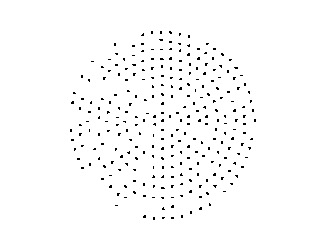
Fig. 5 Reflective laser lattice θ= 4 mrad ( z = 0)
Figure 5 is a light spot diagram at θ = 4 mrad, z = 0. Compared with Figure 1 (shown by a split ray trace), it can be seen that the circles in Figures 1 and 5 correspond one by one, but the azimuth angle of r of each point on the circle changes. The same is true for other θ and O values.
It can be seen from the above analysis that if the incident light is the fundamental mode Gaussian light, the reflected light will form a circular-like spot on the z = 0 plane, it can also be approximated as a Gaussian distribution. For the fundamental mode Gaussian light, the radius of the incident beam refers to the value of w where the amplitude is reduced to 1/e of the central value, and the resulting spot at z = 0 is treated the same way.
We are more concerned about the peak light intensity of the spot, and take the minimum radius of the spot as the equivalent Gaussian radius.
Light intensity distribution:
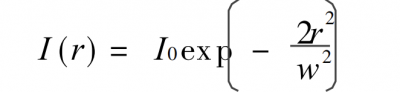
Total power Pt:
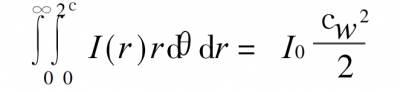
The total power is constant, so
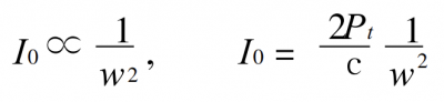
formula 4
The peak light intensity I0 (θ) curve is shown in curve a in Figure 6.
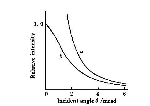
Fig. 6 Peak power density vs misalignment angle θ
In curve a, when θ→0, I0 (θ)→∞, which is obviously unreasonable. This is because when θ→0, the w calculated by the geometric method → 0, and when w is less than the diffraction limit, the influence of diffraction must be considered, and w cannot be infinitely small. When θ→0, the optical path system can be regarded as the focusing process of Gaussian light through a lens (here, CO2 laser is used as an example). θ = 0, the equivalent focal length f′ = f (as shown in Figure 7), there is
formula 6
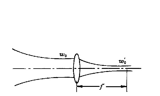
Fig. 7 Equal schematic of the system with precise alignment
When θ>0, two mutually perpendicular focal lines are generated. If the radian of the sagittal focal line is ignored, the reflected light can be regarded as an elliptical Gaussian beam. Among them, the beam waist in the plane parallel to z-x is at the meridional focal line, and the beam waist in the z-y plane is at the sagittal focal line. The equivalent optical path is shown in Figure 8.
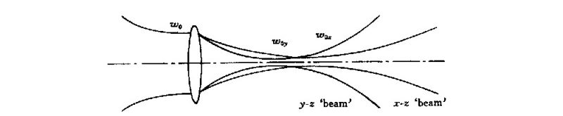
Fig. 8 Equal schematic of the system with misalignment angle
1)
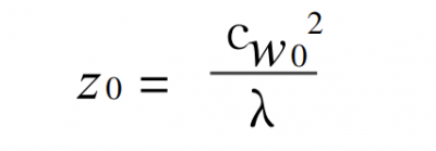
Among them, z0 see formula (6).
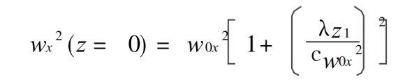
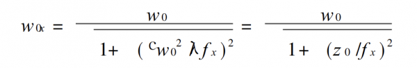
formula 7
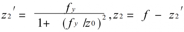
2) have
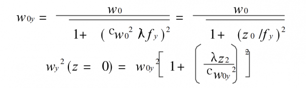
formula 8
Among
3) Find the peak light intensity
For an elliptical Gaussian beam, let the peak light intensity in any z cross-section be I0, then its total power Pt satisfies the following formula

Therefore, its peak light intensity is
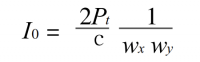
formula 9
The corrected beam spot radius w′ can be obtained from equation (9). Then the modified curve can be obtained by formula (4), as shown in Figure 6, curve b. When θ is extremely small, this correction is reasonable, but when θ is large, the movement of the reflected beam is severely distorted, and it is not like a Gaussian beam at all, so this correction is wrong.
But it must also be located between the a and b curves. It can be seen from the above formulas that the b curve is closely related to the focal length f of the parabolic mirror and the wavelength λ of the laser. During mathematical simulation, changing the value of the focal length f or the wavelength λ, it can be seen that the b curve changes greatly, as shown in Figure 9 (a), (b).
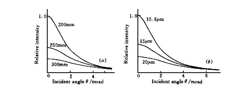
Fig. 9 Peak power density vs misalignment angle θ
(a ) for various focal lengths; (b) for various wavelengths ( f = 200 m m)
The longer the focal length, the larger the Gaussian light spot reflected and focused when there is no declination angle, so that the influence of the geometric light spot (caused by the declination angle) is reduced, so the peak light intensity changes with θ when the focal length is large. The peak light intensity is small, so in practice, a parabolic mirror with a short focal length should be used as much as possible.
However, in laser welding, if the focal length is too short, the contamination of the mirror surface by sputtering will increase, thereby reducing the welding quality and the service life of the mirror.
Under the premise of the same total power and beam diameter, the longer the wavelength, the larger the photon density, and the larger the corresponding Gaussian spot. The result is similar to the analysis in the previous section. It can be seen from Figure 9 that the peak light intensity follows the θ descending pole quick. It can be reduced by half at the declination angle of mrad magnitude, and it can be seen that I0 (θ) is extremely sensitive to θ.
The diameter of the incident beam is different, and the corresponding I0 (θ) curve is also significantly different. When there is no deflection angle, since the total power is constant, the smaller the incident beam radius w0, the greater the photon density corresponding to the focused beam, which in turn makes the beam’s The degree of diffraction is enhanced. Considering that the focal length of the parabolic mirror is constant, the corresponding spot radius on the z = 0 plane is larger, so I0 (θ = 0) is correspondingly smaller.
The misalignment of the optical axis is very large, that is, when the value of θ(h) is large, the size of the geometric light spot on the z = 0 plane will be much larger than the diffraction amount, so the influence of the former is mainly considered.
The geometric spot radius is proportional to w0, so the I0 corresponding to the incident light with a small radius (when the value of θ is large) is larger, as shown in Figure 10. The three curves in the figure correspond to w0 = 20, 15, 10 mm respectively .
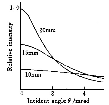
Fig. 10 Peak power density vs misalignment angle θ for various beam radii (f = 200 mm)
It can be seen from Figure 10 that the peak light intensity at no deflection angle is approximately proportional to the square of the incident light radius. This is because the spherical aberration of the parabolic mirror is zero, and a large w0 value will not bring spherical aberration; it can be seen from equation (5) that w0′∝ 1 /w0 is approximately true, and then considering equation (4), we know that I0 (θ) =0) ∝ w0 2 . The larger the incident light radius is, the faster I0 (θ) decreases with the increase of θ, which puts forward higher requirements for the adjustment accuracy of the optical axis.
3 Influence of divergence angle
In the previous discussion, the beam waist of the incident light is located at the mirror surface, that is, the influence of the divergence angle of the incident light can be ignored. However, in practice, it is difficult to ensure the overlap between the beam waist and the mirror surface, and the condenser is often in the far field. The effect of the divergence angle on the focused spot is studied below.
When the divergence angle of the incident light is T, the incident light can be regarded as a spherical beam with a half-angle of T. Easily obtained from geometric optics
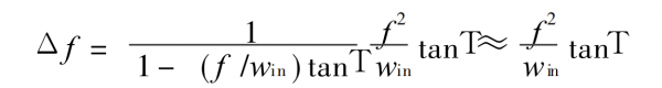
formula 10
Similarly, the light spot on the focal plane of f′= f + Δf under different divergence angles can be obtained by the ray tracing method, as shown in Figure 12.
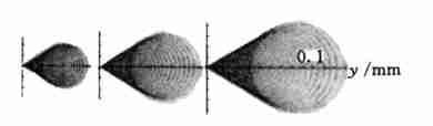
Fig. 12 Coma diagram calculated for divergence angle of 2 mrad , 3 mrad and 4 mrad ( f = 200 mm, w = 20 mm)
The coma aberration is caused by the divergence angle, and the coma tail extends along the y-axis. The coma aberration is formed by the overlapping of two sectors, one large and one small, the large sector corresponds to the incident light in the upper semicircle, and the small sector corresponds to the incident light in the lower semicircle.
Moreover, the light points at the small fan-shaped handle end are dense, which is the peak light intensity. In Fig. 12, Δf takes the exact value, the two sectors are close, and it is difficult to distinguish; when Δf takes the approximate value in formula (10), the large and small sectors are distinct .
The coma disperses the energy at the focal spot, which greatly reduces the peak intensity of the focal spot. With the increase of the divergence angle, the coma scale increases sharply, and the peak intensity decreases sharply, as shown in Figure 12; as the radius of the light increases, the speed becomes faster, see Figure 13.
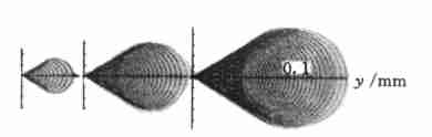
Fig. 13 Coma diagram calculated for beam radius of 10 mm , 20 mm and 30 mm ( f = 200 mm, T= 3 mrad)
This is purely the result of geometrical optics analysis. On its corresponding light intensity map, there is a sharp bulge at the end of the small fan-shaped handle. The bulge and other areas with large light intensity must consider the influence of diffraction and optimize it before they can be optimized. Reasonable.
Secondly, it can also be seen from Fig. 12 that the small fan-shaped handle end, that is, the peak light intensity point, moves outward with the increase of the divergence angle. When T is a negative value, that is, when the incident light is convergent transmission, the approximate equivalent optical path diagram is shown in Figure 14.
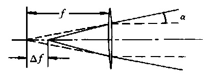
Fig. 14 Equal schematic with divergence angle T which is minus
There are two differences from when T is a positive value: one is that the corresponding focal length f′= f – Δf is shortened; the other is that the tail of the coma is oriented towards the negative y-axis.
4 Conclusion
In this paper, the method of combining geometrical optics and physical optics is used to discuss and analyze the misalignment and divergence of the incident angle of light, aiming at the practical problems that the parabolic mirror is applied to the focusing optical path of the laser beam in the way of 90° off-axis. The effect of angle on the focus spot. conclusion as below:
(1) The angular misalignment converts the incident Gaussian light into an elliptical Gaussian light;
(2) The angular misalignment of the optical axis causes astigmatism and coma, the former will greatly reduce the focused light intensity;
(3) The increase of the diameter of the incident beam will greatly reduce the tolerance to the misalignment of the optical axis angle, and the optical axis needs higher adjustment accuracy;
(4) The increase of the focal length of the parabolic mirror will also reduce the focused light intensity;
(5) Divergence angle will produce coma aberration, which also reduces the focused light intensity.