A few thoughts about optical defects
The definition of the maximum permissible material, surface, and coating defects (imperfections) in the drawing or specifications is established by the designer and based on experience and knowledge. Visible defects, although they impact the perfection of the component, should be defined like any other parameter. Fulfilling the imperfection requirements is a very important issue for all people concerned:
- The designer is concerned that an exceptional defect might affect the functionality of the component or the assembly,
- The producer wants to perform their process and verify conformity to the requirements,
- The customer wants a product that conforms to the requirements, and
- The inspector is responsible for determining conformity.
The existing standards offer guidance for how to the use of comparison standards (gauges) to evaluate the conformity of an existing defect to the standard and to the requirements. However, when evaluating by comparison, there may be large deviations in results from different inspectors (see ASC OP1 ASC OP/TF 2 “Performance-Based Optical Imperfections Task Force Draft Standard Meeting,” August 26, 2007). In order to minimizing conflicts, those differences should be factored into the inspector’s and designer’s decisions.
When certain deviations occur, the following values are taken into account: the size of the deviation (big or small), its place on the item’s surface (on the center or on its side), the location of the item (interior or exterior), the wavelength of the item’s operation (visible or infrared), and sometimes even the contract requirements.
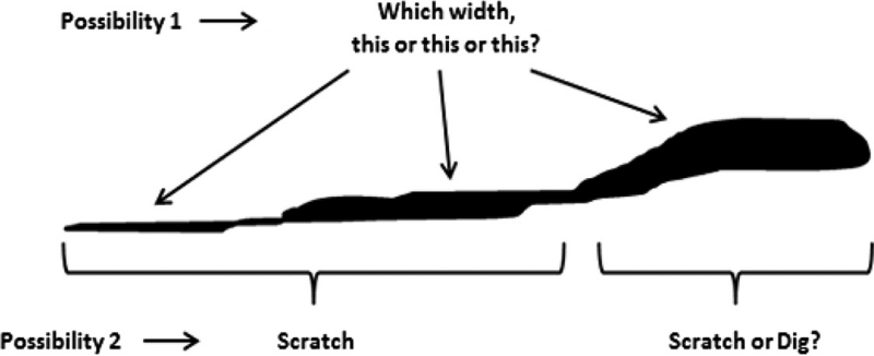
Some disadvantages of the milspecs and the ISO standards necessitate using common sense in decision making. They do not state when a dig (according to the milspecs) or localized imperfection (ISO 10110-7) become a scratch, or what to do if the width of the scratch along its length is not equal or continuous. ISO 10110-7 refers to long scratches, but what about short ones?
This text recommends declaring (in the relevant organizational procedure) that a surface defect with a length that is up to 10 times larger than its width should be considered as a dig; when a surface defect’s length is more than 10 times its width, then the defect should be considered as a scratch. For example, a defect 0.9 mm long and 0.1 mm wide will be considered as a dig, but a defect 0.11 mm long and 0.08 mm wide will be considered as a scratch.
*REMEMBER THAT IN MOST CASES THE OBSERVED DIG DIAMETER IS LARGER THAN THE SCRATCH WIDTH!
Another consideration that should be taken into account is any defect on a sample (test) disk or coated item that passed through environmental tests. The nonconformity of a surface defect should always be treated according to organizational procedures, and a corrective action should be taken to eliminate of any future nonconformity. The following scenarios are real examples of common-sense issues in decision making:
1. Different widths along the scratch (Fig. below). If we take the widest area of the scratch along with its length and the scratch is within the spec, then it should be accepted as conforming to the requirements. However, if the widest area of the scratch is larger than the maximum permissible width, the wide area should be treated as a dig and the remainder as a scratch.
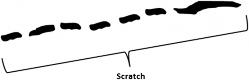
2. A broken scratch.
The decision if it is one long scratch or several short scratches should be made by the inspector. The better choice is the one that gives the lowest result.
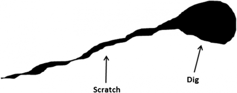
3. A scratch with a dig at the edge.
A scratch is a scratch and a dig is a dig, so treat and evaluate them separately!
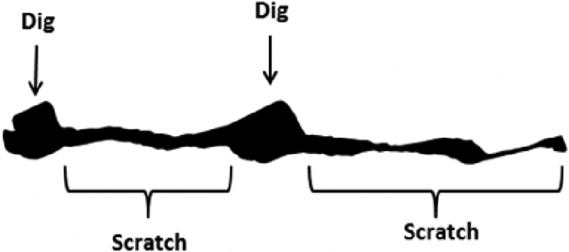
4. Combination of digs and scratches (see below).
This case is similar to the case shown in above and should be treated the same, but if the diameter of the digs is smaller than the maximum permitted width, the collection can be treated as a scratch.
5. Special case of a dig structure.
According to the milspecs, digs are defined by their diameter or by the average of the average of the maximum length and the maximum width.
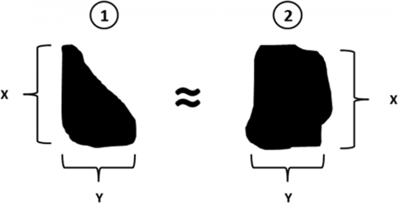

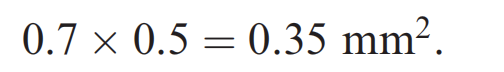
The surface of dig no. 2 is almost twice that of dig no. 1, so, for example, if the stated requirement for scratch-dig numbers is 80-50 (or F-F) and x = 0.7 mm and y = 0.5 mm, then the actual diameter is (0.7 + 0.5)/2 = 0.6 mm, which means that there is a deviation in both digs (dig no. 50 means a diameter of 0.5 mm).
If the values of both digs are reversed into equivalent surfaces, then
The equation for a circle surface is , so the diameter is
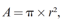
so the diameter is
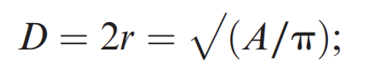
therefore, the equivalent diameter for dig no. 2 will be

but the surface of dig no. 1 is almost half that of dig no. 2 (0.35/2 = 0.175 mm²), so the diameter of dig no. 1 will be

According to the MIL requirements of this example, 0.6 mm supports rejecting the element because it does not conform to the requirement of 0.5 mm. However, further consideration and use of common sense would suggest approving and accepting the deviation (only according to stated organizational procedure). ISO 10110-7 refers to the square root of the localized surface imperfection area, and for cases such as the current example, the result is more precise and more convenient.