Manufacture of Φ420mm off-axis paraboloid mirror
off axis paraboloid mirror, vertical testing of sub-aperture
Abstract
A manufacture and testing technology of Φ420mm off axis paraboloid mirror are reported. The determination principle of manufacture scheme, the choice of start sphere, the calculation of the asphericity of the off axis paraboloid are given. The vertical testing method of sub-aperture of the off-axis surface are on the mother mirror is discussed. The requirement of position accuracy for the testing configuration is analysed. The separating method of the off-axis mirror from the mother mirror is reported. Testing result is given.
Introduction
The aberration-free characteristics of the quadratic aspheric geometric focus make it widely used in large-aperture optical systems. It not only reduces the structure, but also reduces the cost. Because of the unique optical properties of aberration-free collimated beams, parabolic mirrors are often used as collimators as basic optical calibration tools.
The off-axis parabolic mirror reflective collimator is the most simple collimator. Because its central area is not blocked, it has advantages that other forms of collimators cannot match. However, the fabrication of large-aperture, high-precision off-axis parabolic mirrors is very difficult. To a certain extent, its application is limited. There are few reports on the development of large off-axis mirrors with a diameter of more than 200mm in China.
In recent years, we have developed three Φ420mm off-axis parabolic mirrors for a laboratory, and have made useful attempts and explorations on the manufacturing technology of large-diameter, high-precision off-axis parabolic mirrors. In the implementation, the sub-aperture inspection is boldly used to control the parent parabolic mirror shape, thus finally guaranteeing a new method of Φ420mm off-axis mirror shape. The P-V value of the final inspection result of the off-axis parabolic mirror is λ/8.4, which is better than the design index.
The determination of the processing method
1. Basic parameters of Φ420mm off-axis parabolic mirror
- Diameter: D=420mm
- Focal length: F=5000±5 (mm)
- Off-axis angle: α=3.6°
- Surface accuracy: P-V ≤λ/6 (λ=0.6328μm)
2. Determination of process plan Usually, there are two methods for processing off-axis parabolic mirrors
- Single-piece processing: make the glass blank size to the required diameter of the off-axis paraboloid, and then grind it into the required surface by hand or supplemented by a machine shape. It is mainly suitable for off-axis mirror processing with low surface shape accuracy. Only when the technology for computer-controlled optical processing matures, can single-piece machining of high-precision off-axis mirrors become feasible and generally accepted.
- Cut out from a large axisymmetric paraboloid: Grind a large axisymmetric paraboloid (mother mirror) by ordinary methods. Then, dig out the required off-axis parabolic mirror from the casing with a dig round tool. This method is relatively mature in technology, and it is generally believed that it is suitable for mirrors with a diameter of about 100mm and a small off-axis amount.
After repeated demonstrations, we finally chose the processing method of cutting a Φ420mm off-axis paraboloid from a large axisymmetric paraboloid. Obviously, the implementation of this processing scheme on the Φ420mm caliber is a breakthrough to the traditional concept. The basic basis for choosing this processing scheme is:
① Comprehensive analysis The technical index requirements are reasonable and moderate;
② We have the technical conditions and ability to process parabolic primary mirrors above Φ1m;
③ With a vertical inspection tower, vertical inspection can be carried out;
④ Provide users with three off-axis mirrors at the same time, which is economically feasible for both users and manufacturers.
- Calculation of the diameter of the parent paraboloid The parent paraboloid equation is:

As shown in Figure 1, if the height of the optical axis of the off-axis parabolic mirror is h, then

F is the parabolic focal length, and α is the off-axis angle.
Therefore

The effective aperture of the off-axis mirror parent is
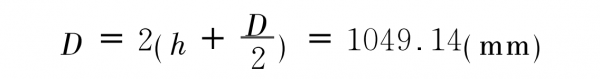
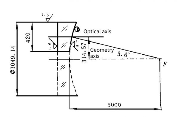
Fig. 1 Basic parameter diagram
Selection of starting spherical surface, calculation of asphericity
The rationality of the selection of the starting spherical surface is related to the size of the asphericity in the processing of the parabolic mirror, and directly determines the processing cycle and cost. Therefore, the selection of the starting sphere and the size of the asphericity play a very important role in the process design.
1. Selection of starting spherical surface
For a paraboloid without a central occlusion, the starting sphere should be a sphere that passes through the edge band and touches the vertex, as shown in Figure 2(a). However, the inner edge of the off-axis mirror (sub-aperture on the parent) to the center of the geometric axis of the parent mirror is the non-working area (blind area), and there is no need to identify it during inspection. Therefore, when the starting sphere is selected, the outer band can be in contact with the edge of the blind zone, as shown in Figure 2(b). The center of the starting sphere must be on the axis of symmetry.
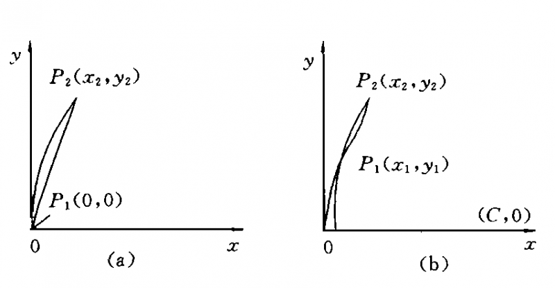
Fig. 2 Starting spherical selection diagram
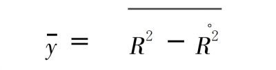
Let its radius be R, its vertex coordinates are not (0, 0), but (ε, 0), so the coordinates of the center of the sphere are (c, 0), not (R, 0), ε=c-R . From the distance formula it can be written

Solutions have to formula C as below
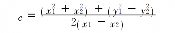
thereby, formula R is

When calculating off-axis parabolic asphericity, ε=c-R must be added. Substitute the coordinate values of the inner and outer edges of the Φ420mm off-axis mirror into equations (1) and (2) to obtain:
Off-axis mirror starting spherical radius
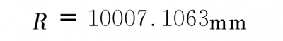
The coordinates of the center of the starting radius are (10007.1075, 0) The starting radius selected in this way can minimize the amount of grinding during processing.
2. Calculation of asphericity
After the initial spherical radius is determined, in order to effectively guide the processing, the grinding amount σ of each belt of the mirror surface must also be calculated. As shown in Fig. 2(b), the off-axis paraboloid in the meridional section ranges from p1 to p2, and the equation of the parent paraboloid is y=2R°x. Therefore, the asphericity σ of each band of the paraboloid (along the X axis) is
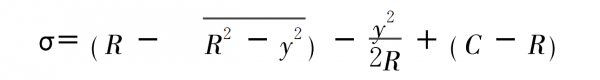
The σ values calculated by this formula are all negative numbers, indicating that the starting spherical surface is to the left of the off-axis mirror. For the concave mirror surface, it is necessary to “repair” the glass instead of wearing it, so the starting sphere needs to be shifted to the right by an amount – The maximum value of all σ values is σmax. In actual processing, the belt corresponding to σmax is not ground, and the grinding amount is the largest at points p1 and p2. That is, the real grinding amount σ

σmax can be obtained by taking the derivative of above formula asphericity σ, formula y
The maximum grinding amount is σmax=0.00133mm.
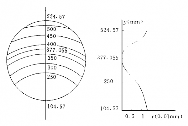
Fig. 3 Grinding Amount Diagram
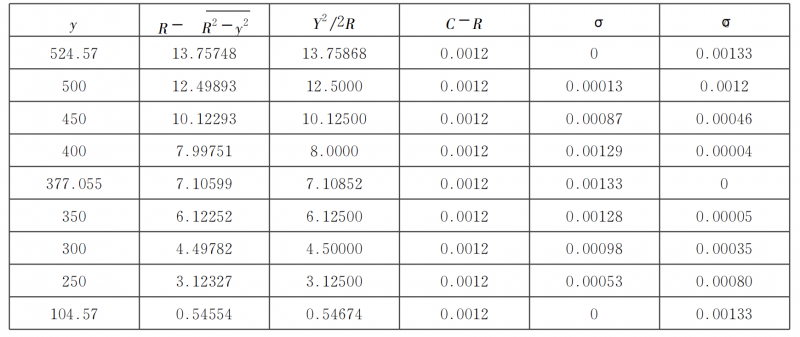
Table 1 shows the relevant quantities of each belt and the final asphericity and grinding quantity according to formula asphericity σ and the formula of the real grinding amount σ, and translation requirements. Figure 3 is a graph of the amount of grinding drawn according to the σ value in Table 1.
Table 1
Vertical inspection of sub-aperture
Accurate inspection is the premise of guiding processing. In a sense, the effective and accurate inspection of the mirror surface in polishing is more important than the processing itself.
1. Sub-aperture vertical inspection
Usually during manual grinding, a plane mirror matched with a parabolic parent is used to form a self-aligning inspection, or a collimator is used to generate a parallel beam, and knife-edge inspection or interference inspection is performed at the focus. Obviously, it is unrealistic to realize self-calibration inspection in the range of caliber up to 1050mm. It is a relatively mature method to use offner compensation method to perform compensation test on paraboloids. However, because the diameter of the paraboloid parent body is too large, it is not easy to turn over during processing, and it is not convenient to form a horizontal detection optical path, but only vertical inspection can be performed. In the vertical inspection, the installation and adjustment of the compensator are extremely difficult and forced to give up.
To this end, we boldly adopted a new inspection method – sub-aperture vertical inspection method. The part of the off-axis sub-aperture required in the paraboloid matrix is listed as the inspection area, and a Φ420mm standard plane mirror is used for self-collimating reflection, and the sub-aperture shadow star point vertical inspection is realized by the knife edge on the geometric focus of the paraboloid matrix. Figure 4 is a vertical inspection light path diagram.
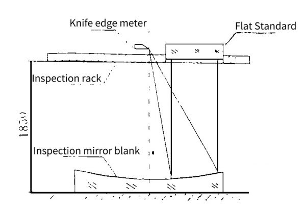
Fig. 4 Optical path diagram of vertical inspection
2. Analysis of inspection accuracy
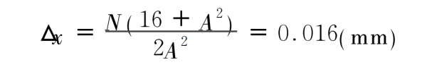
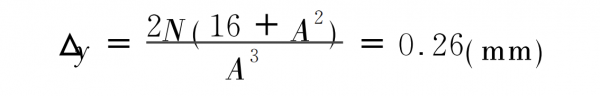
The vertical inspection of sub-apertures during processing is asymmetric inspection. The wavefront deformation caused by the defocusing of the geometric focus and the wavefront deformation caused by the inclination of the standard plane mirror relative to the optical axis will seriously affect the recognition and judgment of the surface shape of the processed mirror. . The following discusses the positioning accuracy between the detection elements in the inspection. The defocusing of the knife-edge star point to the geometric focus can be divided into two cases: axial defocusing and lateral defocusing. According to D. Т. Priyaev’s theoretical formula.
(1) when only the axial defocus
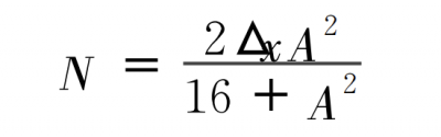
In the formula,
N – defocusing wavefront deformation;
Δx – axial defocusing;
A = 2y/f – is the relative diameter of the paraboloid.
(2) When only laterally defocused
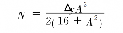
Assuming that the maximum wavefront error allowed by defocusing is λ/8 during inspection, then the maximum allowable axial focus adjustment of the knife-edge star point.
The maximum allowable amount of lateral focus adjustment of knife-edge star point
(3) The allowable amount of the inclination angle error of the plane mirror, according to the precise analytical formula
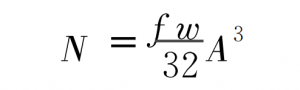
Assuming that the maximum wavefront error allowed by the tilt of the plane mirror is λ/8, then the maximum tilt angle of the plane mirror is
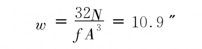
It can be seen that during the inspection, the adjustment of the star point of the knife edge and the placement of the plane mirror are very strict.
Process
The entire process technology implementation process, including: rough grinding, forming, fine grinding, polishing and digging off-axis mirrors and other processes are all carried out on a Φ1.6m mirror grinding machine.
1. Coarse grinding, fine grinding
The technical point of rough grinding and fine grinding is to strictly control the accuracy of the starting spherical radius and the uniformity of the radius on the same annular belt. Check after finishing grinding.
Meridian radius deviation: ΔRy=88mm;
Sagittal radius deviation: ΔRx=92mm;
Astigmatism deviation: ΔR (x-y) max=8mm.
The radial radius is large in the center and small on the side; the radii that are perpendicular to each other have good coincidence, and the deviation is small, that is, the mirror symmetry is good.
2. Polishing
Because the relative diameter D/f of the parabolic parent body is small and the asphericity is not large, the polishing work is divided into two steps. First change the specular highlight to the starting aspheric radius (closest radius). Then on this basis, continue the light modification, that is, asphericization.
The structure radius of each ring zone of the parabolic mirror is different. For the convenience and feasibility of changing the surface shape of the light, we have made 8 polishing pads with different diameters and shapes. First, use the large plate and the middle plate to modify the mirror surface, and then use various small plastic plates to shave the surface. After the spherical aberration is eliminated, a large-diameter plastic disc is finally used to smooth the entire mirror surface to the design surface shape accuracy requirements.
3. Quantitative final inspection
The timely inspection of the sub-aperture in the polishing process is a qualitative inspection and cannot provide quantitative inspection data. After the processing is completed, we use the method of chemical coating to coat the effective sub-aperture part of the paraboloid parent with chemical silver film to increase the reflectivity of the coated surface. Quantitative laser interferometry was then performed on the mirror surface. Figure 5 is the inspection light path diagram.
The interference fringe sampling processing results, the surface shape accuracy reaches λ/8.4, and passes the user’s acceptance.
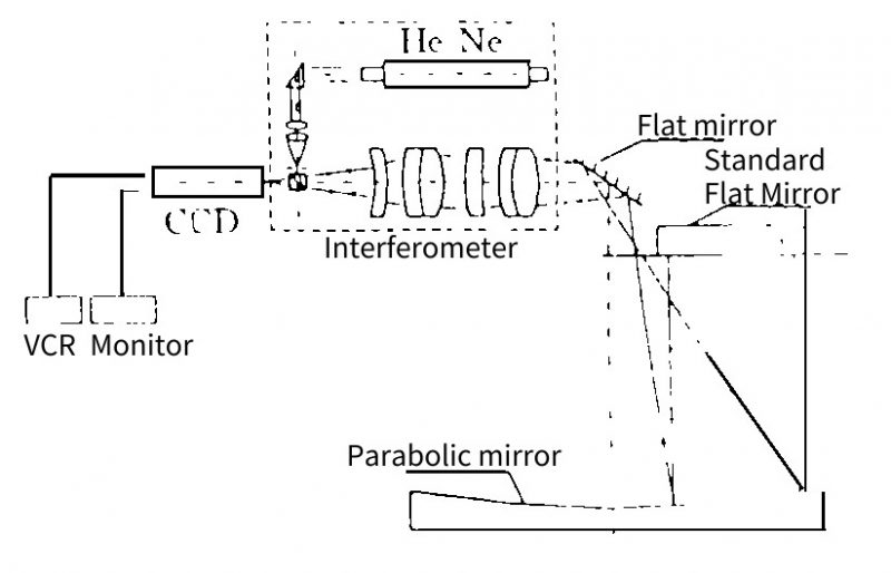
Fig. 5 Inspection light path diagram
4. Set of digging
How to keep the mirror surface from being damaged and scratched in the sleeve excavation is the core problem of sleeve excavation off-axis mirror.
To this end, before digging, first brush a pure glue layer with a thickness of about 5mm on the mirror surface to protect the mirror surface.
It effectively blocks water and sand from immersing in the mirror surface during sleeve digging. The sleeve round tool is surrounded by three steel sheets with a thickness of about 3mm to form an open cylinder, and a 1.2m radial drilling machine is used as the rotational driving force for the sleeve digging.
During sleeve digging, the speed is 60r/min, and the manual micro-feed is used. The mirror cover was dug into a Φ420mm off-axis mirror and re-checked, and the surface shape accuracy did not change.
We have completed the processing by adopting the method of trimming the tape of the small plate, smoothing the large plate, and gradually advancing. The processing of Φ300mm, Φ410mm, Φ470mm spherical light reflector and Φ630mm aspherical light reflector is completed by the above processing method. Figure 7 shows the shape of the Φ470mm light spherical fused silica reflecting mirror measured by ZYGO Mark IV laser interferometer, and the PV value is 0. 117λ, the RMS value is 0.024λ (λ=632.8nm)
Development of high-efficiency broadband reflective film
In order to ensure that the fused silica light reflector has a very high reflectivity at 3.8μm, and at the same time make the visible and infrared regions have a high reflectivity, Ag is selected as the reflective film material. In order to enhance the reflectivity of the silver film at 3.8μm, and at the same time to ensure high reflectivity in the visible and infrared bands, the selected medium must have low light absorption from the visible to infrared bands. Based on this requirement, ThF4, YbF2, PbF2, BaF2, etc. can be used as low-refractive index materials, and ZnSe, ZnS can be used as high-refractive index materials. In the comprehensive analysis, we choose YbF3 and ZnS as the enhanced high and low refractive index film pair for the Ag layer.
As far as the light-weight primary mirror is concerned, in order to ensure high reflectivity in the visible region, we choose a pair of dielectric films. The whole membrane system is designed as: Sub/Ag (YbF3/ZnS) Air.
The relative measurement was carried out with a Hitachi 340 spectrophotometer.
The standard reflector was an all-dielectric band total reflection film developed by Optoelectronics, and the reflectivity was greater than 99.99%. 5%.
The reflectance measurement results are as follows: 0.50μm ~ 0.85μm reflectivity greater than 98.5%;
The reflectivity of 30μm is greater than 99.5%; 8.00μm ~ 12.00μm reflectivity greater than 97.0%.
The light-duty fused silica mirror film has been tested in humidity, high and low temperature and salt water, and all conditions of the test meet the requirements of GB1320-77.