Manufacture of an aluminum alloy off-axis parabolic mirror
off-axis paraboloid, slow-tool servo turning method, aberration-free method
Summary
Aluminum alloy off-axis parabolic mirrors have been used more and more in optoelectronic equipment due to their ease of processing, economy, and suitability for use in low temperature and variable temperature environments. In this paper, by using the single-point diamond turning process, the main parameters affecting the surface shape machining accuracy in slow-tool servo turning and the aberration-free measurement plan for the surface shape are studied. An economical and reliable process method, the results show that the surface shape of the aluminum alloy off-axis parabolic mirror with a diameter of 120mm can reach 1/3λ RMS by the slow-tool servo turning method, and the process is stable and meets the needs of use.
0 Introduction
Aspheric optical parts have become very important optical parts because of their excellent optical properties, and are widely used in aerospace, military, commercial and other fields. In recent years, off-axis aspheric mirrors have been used more and more in optoelectronic equipment due to their unique structural advantages, and off-axis parabolic mirrors are one of the most typical ones.
The processing of aluminum alloy aspherical mirrors can be formed by existing processes such as turning, milling, and grinding, and processed into aspherical mirrors by diamond single-point turning technology, which is more economical and efficient than glass aspherical mirrors. At the same time, the expansion coefficient of the aluminum alloy mirror and the metal material of the mounting support structure is relatively close, which reduces the influence of the mismatch of the expansion coefficient, avoids the thermal stress and strain caused by the inconsistent expansion coefficient of the optical-mechanical system material, and is beneficial to the mirror surface shape and long-term maintenance of optical system parameters, especially suitable for optical systems working in low temperature and variable temperature environments. This paper introduces a processing method of an off-axis parabolic mirror based on the off-axis parabolic mirror used in a multi-optical axis calibration instrument of a product of the company.
1 Processing of off-axis parabolic mirrors
The diameter of the off-axis parabolic mirror is 120mm, the off-axis amount is 150±1mm, the vertex curvature is R2000±2mm, and the material is AL6061-T6 aluminum alloy.
1.1 Processing method of off-axis parabolic mirror
The turning methods of off-axis parabolic mirrors usually include coaxial turning and slow-tool servo turning. The coaxial turning method is to make the axis of the paraboloid coaxial with the rotation center of the main shaft, cut it in a conventional rotationally symmetric way, and then remove the required off-axis part. Its advantages are high surface accuracy, good surface roughness and simple machining procedures , the disadvantage is that it cannot be processed by machine tools with large off-axis and large diameter aspheric mirrors.
The slow-tool servo turning method is to make the geometric center of the off-axis parabolic mirror coaxial with the spindle rotation center, and use the slow-tool servo method for turning, which is almost the opposite of the coaxial turning method. Limited by the X-axis travel of the company’s existing single-point diamond lathe, the machine tool cannot use the coaxial turning method, so the slow-tool servo turning method is used for processing. The schematic and processing of the slow-tool servo turning method are shown in Figure 1 and Figure 2.
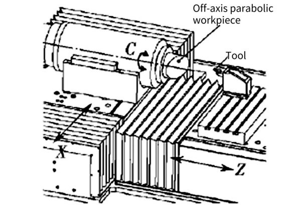
Fig.1 Schematic diagram of slow tool servo turning method
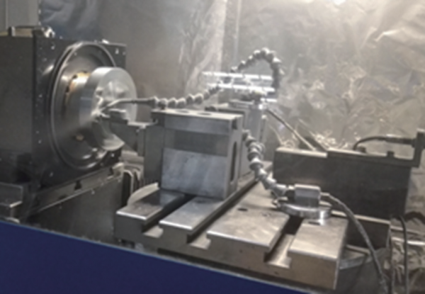
Figure 2 Cutting diagram
1.2 Processing flow
①Tool preparation.
Make a special jig (as shown in Figure 3), the jig includes screw holes connected with the main shaft of the equipment, a vacuum air path and a positioning pin for positioning the workpiece;
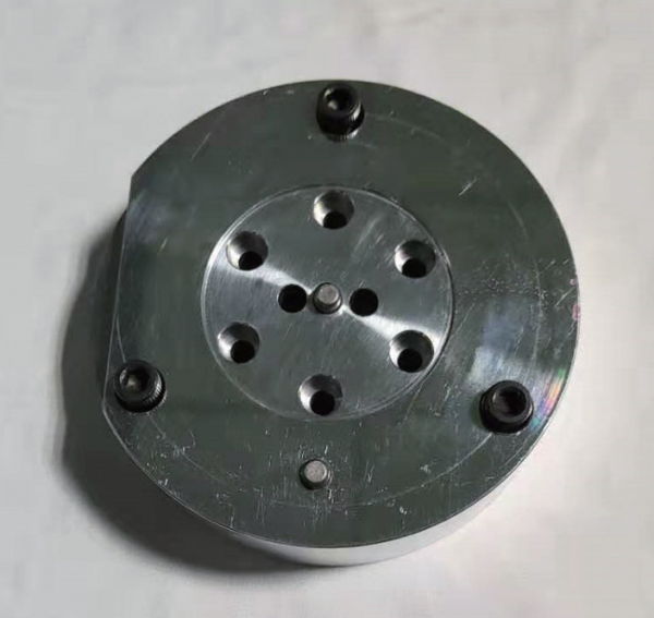
Figure 3 Special jig
Make the inclined plane tool setting (as shown in Figure 4) and the workpiece blank;
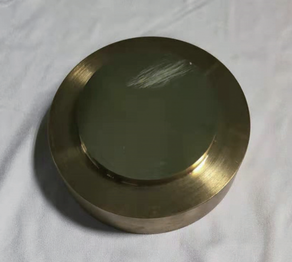
Figure 4 Inclined plane tool setting
To prepare the cutting tool, this article selects the natural diamond tool from Contour Tools, UK. The rake angle of the tool is 0°, the relief angle is -10°, the edge radius is 0.75mm, the waviness cone control is less than 0.25um, and the model is C0.75mLGC/0.25 um.
② parts clamping
Remove the C-axis vacuum suction cup and coolant cover of the single-point lathe, install the special jig on the C-axis with half-tight screws, and use a lever dial indicator and a small mallet to adjust the circular runout of the jig, adjust it to ≤ 1um, and then lock and fix it ; Install the turning tool at the T1 position, and use the optical tool setter to measure the cutting edge radius and absolute coordinate position of the tool, and save them to the UPX system.
③ Activate the C axis
Input command: M27.1, activate the C axis, turn the ROTARY button on the console panel to “C”; input command G92 to clear the compensation; level the fixture positioning platform along the X direction, B+ and B- control the C axis rotation, use The lever dial gauge measures the parallel inclination of the positioning platform along the X direction is better than 2um, and then in the tool menu of the UPX system T1, the C axis “Load Current Position” in the T2 tool or directly input the command: G92C0.
④ Tool alignment
Turn the ROTARY knob to “B”, use the OFHC oxygen-free copper baseball to face the tool for tool setting, adjust the tool offset in the Y and X directions to be accurate, it is required that the cylindrical or conical convex hull can hardly be seen under the 100X tool microscope, use The PGI profiler of Taylor Hobson Company detects the Delta X ≤ 1um of the surface; ⑤ Fine-tune the tool. Turn the ROTARY knob to “C”, install the inclined plane workpiece, perform precise tool setting by using the digital laser wavefront interferometer, write the inclined plane turning program in Diffsys, and measure the inclined plane shape through the part in the interferogram after turning. The X Profile and Y Profile values are used to fine tune the tool offset.
⑥ Turning
After the tool offset is adjusted, write the part processing program in Diffsys, install the part, and carry out cutting processing. The X Increment in the rough cutting parameters is set to 0.05mm, the feed is 0.02 ~ 0.04mm, and the X Increment in the finishing cutting parameters is set to 0.01mm , the feed is 0.002 ~ 0.004mm.
2 Measurement of off-axis parabolic mirrors
Generally, the measurement of optical aspheric surfaces adopts special measuring instruments, and special software needs to be configured for off-axis aspheric surfaces, which is not only expensive, but also has many limitations. For the special off-axis aspheric surface such as the off-axis paraboloid, the detection method based on spherical interferometer can be used.
2.1 Measurement method — build an off-axis paraboloid measurement platform
In this paper, the WYKO RT6100 laser wavefront interferometer is used to build the following detection optical path. It mainly uses a pair of aberration-free conjugate points on the secondary aspheric surface, and introduces auxiliary optical elements into the detection optical path to form a self-collimating optical path for detection. The spherical reentry mirror is adjusted so that the focus of the off-axis parabolic mirror is conjugated with the center of the sphere. The schematic diagram of the detection optical path is shown in Figure 5.
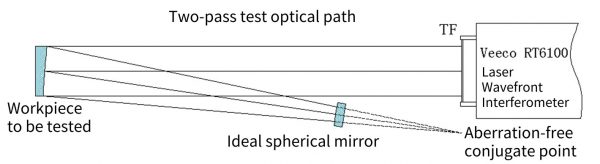
Fig. 5 Detection optical path
2.2 Clamping influence analysis and its optimization scheme
The optical system simulation of the measurement platform was carried out using Zemax software, and the following wavefront analysis was obtained. It can be seen from Figure 6, Figure 7, and Figure 8 that the adjustment accuracy of the interference optical cavity has a significant impact on the detection results. When installing the parts, it is necessary to level the off-axis parabolic mirror on the sagittal plane and the meridional plane as much as possible to avoid the image caused by this. Astigmatism, field curvature, coma and other measurement errors, and at the same time use the five-dimensional adjustment frame to adjust the position of the spherical return mirror to obtain the minimum value of the interference wavefront, so as to accurately reflect the surface shape error of the part itself.
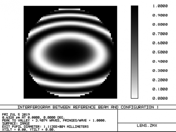
Fig.6 Sagittal plane Tilt 0.3°
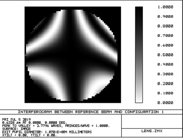
Fig.7 Tilt 0.3° on the meridian plane
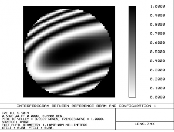
Fig.8 Tilt0.3° on both sagittal and meridional planes
Design a measuring tool (see Figure 9), remove the original three-claw structure, and install it on the five-dimensional adjustment frame of the horizontal laser wavefront interferometer. First, use a mirror with good parallelism and flatness to align the workpiece positioning surface with the interferometer. The optical path is adjusted and aligned, and then the workpiece is installed on the measuring tool through the positioning pin, and the position of the workpiece and the spherical return mirror is fine-tuned, and the change of the interference fringes is observed to minimize the astigmatism, so as to obtain a good interference cavity.
Fig. 9 Special tooling for measuring and clamping
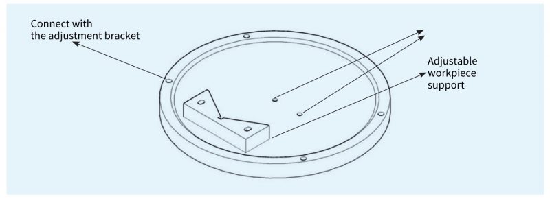
Fig. 9 Special tooling for measuring and clamping
2.3 Verification of the accuracy of the detection method used in this paper
Use the Luphoscan420 non-contact aspheric measuring system to perform absolute surface measurement, and obtain PV=2.063um in the workpiece aperture (see Figure 10). The measuring platform used in this paper measures PV=2.136um (see Figure 11). Therefore, the The measurement method is accurate and reliable.
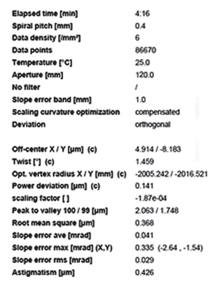
Fig. 10 Luphoscan420 measurements
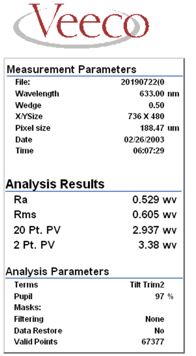
Fig. 11 The measured values of the interferometric platform in this paper
3 Process optimization and result analysis
3.1 Process optimization of slow-tool servo turning method
In slow-tool servo turning, the tool centering error has a great influence on the machined surface. Generally speaking, the three angles of the tool attitude are guaranteed by the installation, and the error has little influence on the machining surface shape. The Z-axis direction is the direction of the depth of cut, which has no effect on the shape of the machined surface. The centering error of tool height and level is the most important factor. In this paper, the slow-tool servo cutting of the tool with inclined plane and the laser wavefront interferometer are used to adjust the tool offset more accurately. The XProfile and Y Profile curves obtained by measuring the tool on the inclined plane under the interferometer are symmetrical, and there is no center error, so the tool offset can be accurately adjusted. Figure 12 and Figure 13 show the interference diagram of the inclined plane with the tool after the ideal centering of the tool, and the surface shape of the workpiece after further optimization is shown in Figure 14 and Figure 15.
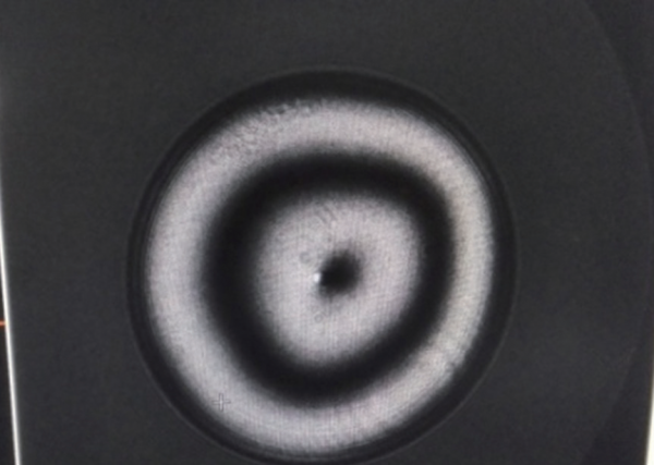
Fig. 12 Interference diagram of the inclined plane on the tool
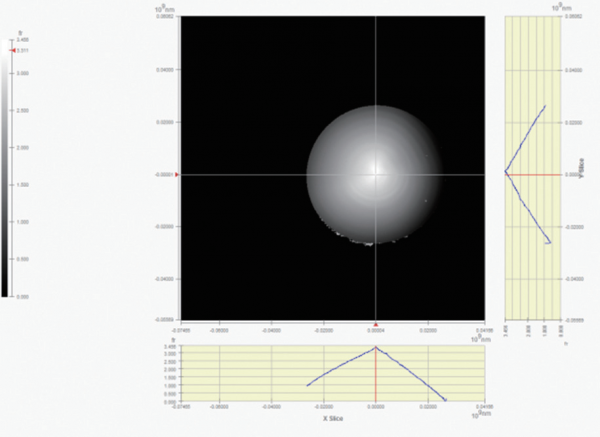
Fig. 13 Profile of the X and Y directions of the surface of the inclined plane for the tool part
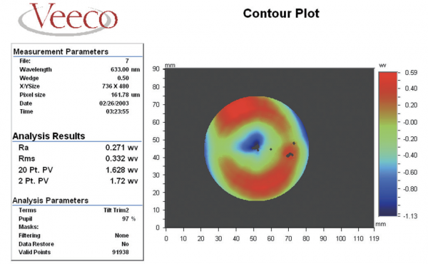
Fig. 14 Surface shape (PV: 1.08um, RMS: 0.207um)
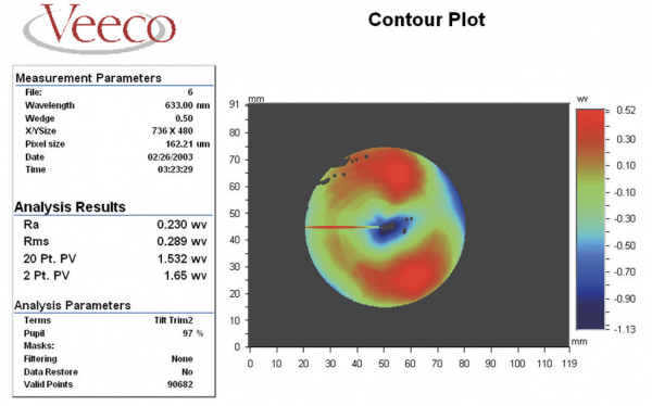
Fig. 15 Surface(PV:1.04um,RMS:0.183um)
3.2 Result analysis
The machining results show that the off-axis parabolic mirror is machined by the slow-tool servo turning method, and the precision of the machining surface shape can reach 1/3λ RMS by using the tool-setting trial cutting and the laser wavefront interferometer to fine-tune the tool centering position, has good process stability and economy, and meets the needs of our factory for this type of parts.
4 Conclusions
For off-axis aspheric surfaces with large off-axis and moderate precision, using slow-tool servo turning method is an economical and reliable machining method. The offset surface shape accuracy of the diamond tool has a great influence. The cutting of the inclined plane can be used to test the tool setting accuracy. After adjustment, the surface shape accuracy of the workpiece can meet the general requirements. The off-axis paraboloid is a kind of free-form surface, but for the quadratic surface, the laser wavefront interferometer can still be used for relative measurement using the aberration-free point method.