Design of optical lens for terahertz detector array using Tracepro
terahertz; detector array; Tracepro; optical lens
Abstract
Terahertz imaging technology is a rising detection technology with great development prospects. In order to satisfy the requirement for terahertz detector array imaging,,a compact refractive optical lens is designed. The lens material is HRFZ-Si with a parylene anti-reflection coating on the surface. The imaging on the focal plane of the point at infinity on the axis and off axis through the optical lens is silmulated by using Tracepro software, and the structural parameters of the optical lens are optimized. The optimizing lens simulation results indicate that the focal length of the optical lens is 26.2mm, the filed angle is 16.3°,the relative aperture is 1.9: 1 and the resolution is 20 Ip/mm.
1 Introduction
Terahertz waves are in the transition region between electronics and photonics, and their unique properties have attracted increasing interest in the scientific community. Terahertz detection imaging is an important direction for the application of terahertz technology.
Uncooled array thermal detectors have the characteristics of low cost, light weight, reliability and broadband, and research institutions in the United States, Japan, Canada and other countries have made them the focus of terahertz detector research.
Tracepro is a set of optical design and simulation software generally applicable to lighting systems, optical analysis, radiometric analysis and photometric analysis.
In this paper, based on the basic theory of applied optics, a refractive optical lens is designed for a terahertz detection array with a detection array size of 80 × 60 and a detection pixel size of 75 μm.
The Tracepro optical simulation software is used to simulate the imaging situation of the infinity point passing through the designed optical lens on the focal plane, and the structural parameters of the optical lens are optimized.
2 Optical structure design
There are generally three types of optical lens structure designs for terahertz microbolometers: reflection type, refraction type, and reflection-refractive type. The schematic diagrams of the three optical structures are shown in Figure 1.
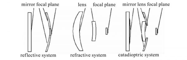
Fig.1 Three optical structures
(reflective system, refractive system, catadioptric system)
The advantage of the reflective structure is that the transmittance of the terahertz wave passing through the material does not need to be considered, only the material with high reflectivity needs to be considered (the gold-coated mirror has a reflectivity of nearly 100% for the terahertz wave).
However, for the detection optical structure which should have a relatively large field of view and a small aperture coefficient, it is difficult to correct the aberration caused by adopting the reflective design. The advantage of the refractive structure is that the aberration can be better corrected by adjusting the size of the optical element, but it will be restricted by the transmittance of the optical element to the terahertz wave.
The reflection-refractive structure can correct aberrations better, and its transmittance is higher than that of the refractive structure (the number of terahertz waves passing through the optical elements is less than that of the refractive structure), but its structure is relatively complex. In line with the principle that the optical structure should be as simple as possible under the premise of meeting the requirements, and the terahertz wave transmittance of the reflection-refractive structure is not qualitatively improved compared with the refractive structure, the refractive structure is selected as the terahertz micrometer. The basic structure of the bolometer optical lens.
2.1 Material selection of optical components
The refractive structure will be restricted by the transmittance of optical components to terahertz waves, so the design of the optical structure of the terahertz detection array should select materials with low absorption rate of terahertz waves as the lens material, and add an effective anti-reflection film to reduce Reflection of terahertz waves on lens surfaces.
Most materials have a high absorption rate for terahertz waves, but some polymers show good permeability, such as TPX (poly4-methylpentene-1), HDPE (high density polyethylene), Picarin (polytetrafluoroethylene) and so on. The absorption rate of these polymer materials is about 4%/mm. To ensure a high transmittance of terahertz waves, a thin lens (generally 2 to 3 mm) must be used, otherwise there will be a large loss (10 mm). mm thickness is about 40% loss). At the same time, the refractive index of these polymers is around 1.5, and the smaller refractive index and thinner lens thickness will limit the correction of aberrations.
The only requirement to achieve image quality is to increase the number of lenses, which increases the complexity of the optical structure and increases the loss of terahertz waves.
Another material that exhibits excellent performance in the terahertz band is high-resistance floating-zone silicon (HRFZ-Si), which has an absorption rate between 0.2%/mm and 1%/mm. Low absorptivity allows thicker lens thicknesses.
The refractive index of HRFZ-Si is about 3.4, the large refractive index and thick lens thickness can easily correct the aberration, and the double-lens structure can meet the image quality requirements. However, HRFZ-Si has a large refractive index and a large surface reflectivity, but the transmittance of terahertz waves is relatively low. The transmittance and reflectivity are shown in Fig. 2.
Fig.2 Transmission and reflection of HRFZ-Si 5mm-thick sample in THz range
In order to increase the transmittance of terahertz wave and reduce its reflectivity, it is necessary to coat the surface of HRFZ-Si with an effective anti-reflection film. Parylene (parylene) film can effectively reduce the reflectivity of THz waves on the lens surface, and is an effective anti-reflection film.
The transmittance of the lens coated with parylene anti-reflection film can be increased from 50% to 60% before coating to 80% to 90%.
Therefore, HRFZ-Si is selected as the material of the refractive optical lens lens, and a parylene anti-reflection film is coated on its surface to enhance the transmittance of terahertz waves.
2.2 Design of optical structure parameters
There are four main parameters that describe the properties of optical structures: Focal length f’, relative aperture D/f’, field angle 2ω and resolution N.
The focal length determines the proportion of the object image, the relative aperture determines the illuminance of the image plane, the field of view determines the spatial range of imaging, and the resolution represents the ability to distinguish the details of the object to be measured. The field of view determines the spatial range of imaging, which is determined by the photosensitive size of the detector and the focal length of the optical structure. The field of view is:

Among them, y’max is the length of the diagonal of the detection array.
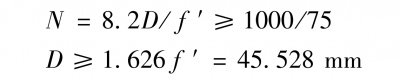
The size of the terahertz detection array designed in this paper is 80 × 60, and the size of the detection pixel is 75 μm. To meet the requirement of 15° for the angle of view 2ω, the focal length f’ should meet:

The resolution of the optical structure should be greater than the resolution of the detection array, and the detection frequency of the detector is around 3 THz, that is, the wavelength λ = 100 μm, according to the Rayleigh criterion:

The entrance pupil diameter D should satisfy:
The relative aperture determines the illuminance of the image plane. The larger the relative aperture, the stronger the light energy reaching the detection array.
According to the photometric theory, the formula for the illuminance of the image point on the axis is:
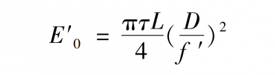
Among them, L is the brightness of the measured object; τ is the transmittance of the optical structure. The energy of terahertz sources is relatively weak, so a large relative aperture is required, which is in line with the size requirements of the optical structure for resolution.
The refracting optical structure adopts the double-lens structure shown in Fig. 1. The first lens is a convex-concave lens, which converges the light beam emitted by the measured object and forms an image, and the second lens is a concentric meniscus lens, which is used to correct aberrations. The third block is the terahertz wave entrance window, which is used to encapsulate and protect the detector.
The initial structural dimensions of the two lenses should be set to satisfy the above-mentioned optical structural parameters. According to the thick lens base point position and focal length formula:
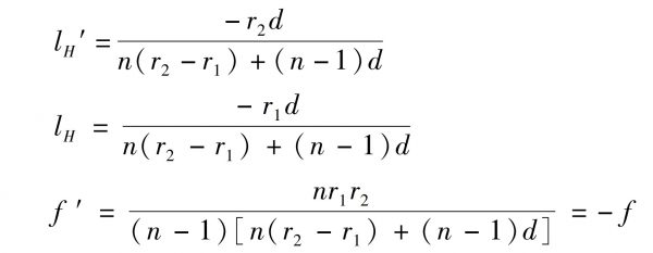
Among them, lH‘ and lH are the position of the base point of the image square and the base point of the object side, respectively; f’ and f are the focal length of the image side and the focal length of the object side of the thick lens, respectively; r1 and r2 are the radius of curvature of the front surface and the rear surface of the thick lens, respectively. Radius of curvature; n is the refractive index of the thick lens material; d is the thickness of the lens.
The formula for the composite image of the two-light group:
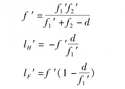
Among them, f’ is the focal length of the two-optical group image side; lH‘ is the base point position of the two-optical group image square; lF‘ is the focal position of the two-optical group image square, f1‘ and f2‘ are the first lens in the two-optical group and f2‘ respectively. The image-side focal length of the second lens; d is the distance between the first lens and the second lens.
When λ=100 μm, the refractive index of HRFZ-Si is about 3.422, and the initial structure of the probe optical structure can be obtained:
- The first convex-concave lens: the curvature radii of the front and rear surfaces r11 = 40 mm, r12 = 97 mm, the lens thickness d1 = 10 mm, the focal length f1‘ = 25 mm, and the diameter D1 = 50 mm;
- The second concentric meniscus lens: the radius of curvature of the front and rear surfaces is r21 = -100 mm, r22 = -105 mm, the thickness of the lens is d2 = 5 mm, the focal length is f2‘ = -2967 mm, and the diameter D2 = 30 mm;
- The third block is a THz wave incident window whose two sides are flat, with a thickness of d3 = 2 mm and a diameter of D3 = 15 mm;
- The distance between the rear surface of the second lens and the front surface of the third lens is d23 = 8 mm;
- The distance between the focal plane and the rear surface of the third lens d34 = 1mm;
- The focal length of the system is f’=26 mm, and the field of view is 2ω=16.4°
3 Optical structure simulation and optimization
Based on the above design, an optical lens model is established in Tracepro, as shown in Figure 3.
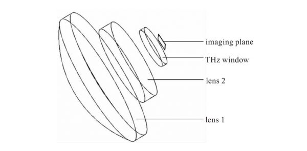
Fig.3 Model of Optical lens
The Grid Raytrace in Tracepro is used to trace the established model. In order to observe the illumination details on the focal plane, the illumination is set to be displayed on a logarithmic scale. The simulation results are shown in Figure 4.
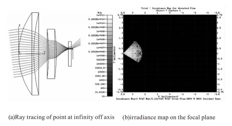
Fig.4 Simulation Results
Figure 4 reflects the imaging situation on the focal plane of the light emitted by the off-axis point at infinity through the designed optical lens.
It can be seen that the light emitted by the point at infinity will converge on the focal plane through the designed optical lens, but due to the influence of aberration, it does not converge to a point on the focal plane, but forms a diffused spot.
The effective radius of the speckle is 75 μm, and the optical resolution is smaller than that of the detection array, which requires optimization of the structural parameters of the designed optical lens to improve the imaging quality.
The incident angle of the light from the off-axis point shown in Fig. 4 is ω (that is, half of the field of view), and it can converge on the detection array, but due to aberration, a part of the light overflows the detection array. This shows that the designed optical structure can meet the requirements of the angle of view.
The designed optical lens can be optimized by adjusting the size and position of each optical element.
The terahertz entrance window is a lens with two planes, which will introduce aberration, and the thicker the aberration, the greater the aberration, so the thinner the window, the better.
However, considering the actual processing and packaging, the original 2mm thick window was reduced to 1mm. After the window is thinned, the light convergence will be more concentrated in the focal point, and the effective radius of the diffused spot will be smaller.
Considering the image of an off-axis point at infinity on the focal plane, the image quality can be improved by adjusting the size and position of the first convex-concave lens and the second concentric meniscus lens.
A set of optical structure parameters with better imaging quality are obtained by optimization:
- The first convex-concave lens: the curvature radii of the front and rear surfaces are r11 = 45 mm, r12 = 147.67 mm, the lens thickness is d1 = 10 mm, the focal length is f1‘ = 25 mm, and the diameter is D1 = 50 mm;
- The second concentric meniscus lens: the curvature radii of the front and rear surfaces are r21 = -80 mm, r22 = -85 mm, the lens thickness d2 = 5 mm, the focal length f2‘ = -1921.5 mm, and the diameter D2 = 30 mm;
- The distance between the rear surface of the first lens and the front surface of the second lens is d12 = 10 mm;
- The third block is a THz wave incident window whose two sides are flat, with a thickness of d3 = 1 mm and a diameter of D3 = 15 mm;
- The distance between the rear surface of the second lens and the front surface of the third lens is d23 = 9 mm;
- The distance between the focal plane and the rear surface of the third lens d34 = 1.1 mm;
- The focal length of the system is f’=26.2 mm, and the field of view angle is 2ω=16.3°.
The comparison of the structures before and after optimization and the imaging situation on the focal plane is shown in Figure 5.
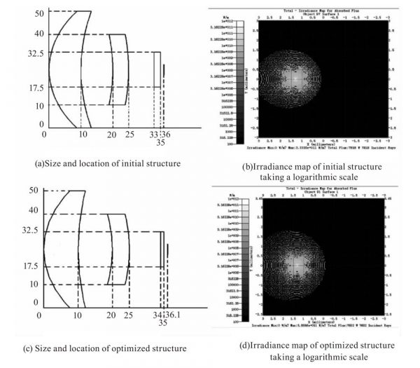
Fig.5 Size location and imaging of initial structure and optimized structure
In the optimized structure, although the light distribution radius on the focal plane is larger, more light is concentrated near the focal point, and the light distribution at the position deviating from the focal point is more sparse and the power density is smaller. reduced to 25 μm after optimization.
The resolution of the optical lens is improved from 6.67 lp/mm to 20 lp/mm, which is optimized from less than the resolution of the detection array to greater than its resolution, which meets the design requirements.
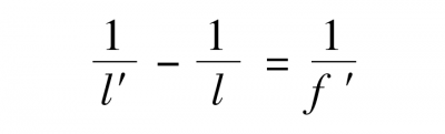
The detection range of the detector is from 1m to infinity, so it is necessary to set the focus range. According to the Gaussian formula for lens imaging:
The distance between the image point at infinity and the image point at 1 m is 0.7 mm away. Taking into account the processing error of the lens and the assembly error during packaging, the focusing range of the lens is set to 4 mm.
4 Conclusion
In this paper, a refractive optical lens suitable for terahertz detection array is designed, and the designed optical lens is simulated by Tracepro software, and good size parameters are obtained after optimization.
The designed optical lens has a field of view of 16.3° and a resolution of 20 lp/mm, which can meet the imaging requirements of terahertz detection arrays.
However, for terahertz detection arrays with larger arrays and smaller detection units, the designed optical structure may restrict, and further improvement is required. The use of aspherical lenses can further improve aberrations and improve the imaging quality of optical lenses.