Lens design and verification used for terahertz space transmission
terahertz, lens, lasers, transmission
Abstract
Terahertz beams are a kind of Gaussian beam with a big divergence angle and its wave front cannot be simplified to a plane or a spherical wave.All the theoretical derivations from the classical electro magnetic theory and ABCD laws support the following conclusions:
Firstly, a positive lens converges the terahertz beam in front of the focal plane instead of oil the focal plane;
Secondly, a negative lens which matches the radius of the Gaussian beam’s wave front is more appropriate for terahertz beam collimation.
Experiments show that a negative lens with f’=-188 mm at the matching position, z=100mm, can improve the terahertz beam collimation from 6° to 0.1°. And 20-m terahertz space transmission was realized with a very simple optical scheme.
Introduction
A terahertz (THz) wave is a type of electromagnetic wave with a frequency between 0.1 and 10 THz. Both the optical and electric methods can generate terahertz radiation. However, limited by the device size, electric methods cannot generate the terahertz radiations above 1 THz, and the devices are fragile. Based on difference frequency generation(DFG)of light and quantum cascade lasers(QCLs), the radiations can cover the full terahertz wave band. Therefore, optically-generated terahertz emission is the preferred source of terahertz radiation. However, the poor efficiency of DFG, small effective emission cross-section of QCLs, and high atmospheric absorptivity drive us to find the best transmission medium for THz wave’s transmission. Several studies show that free space transmission is more advantageous than any other transmission modes such as a metallic waveguide.
A positive lens is usually used for the detection of because it can easily make full use terahertz wave of the terahertz energy, which is favorable to the free space transmission. However, a positive lens has little effect in improving the terahertz beam collimation. Owing to the limitations of terahertz sources and detectors, this study has not yet been conducted. In this paper, the difference between terahertz waves and visible lasers was studied in detail. Theoretical derivations show that negative lenses are more advantageous for terahertz beam collimation than positive lenses. The method to determine the f-number for negative lenses is also given in this paper. The experimental results demonstrated the validity of the theoretical derivations.
1. Theoretical Analysis
1.1 Classical Electromagnetic Theory
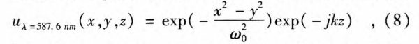
The terahertz source based on the optical method essentially is the stimulated radiative transition of a molecule. Therefore, the terahertz source is a type of laser, and it can be described by Gaussian optics:
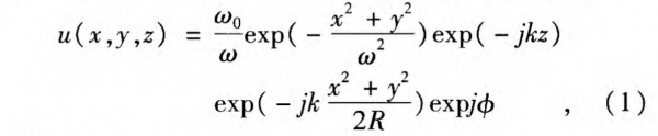
where
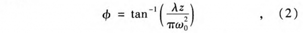
Fig.1 Gaussian beam transmission along the z-axis. ω0 is the beam waist, r is the distance between point(x, y)and the z-axis, R is the spherical wave radius, and W is the spot radius transmission along the z-axis
The schematic diagram of terahertz wave front is shown in Fig. 1, where ω0 is the beam waist at the position z=0, R is the spherical wave radius, and ω is the spot radius along the z-axis. In Eq.1, u (x, y, z) is the field amplitude of the lowest-order mode along the z-axis, where z is the distance between the wave front and laser waist; r= √x² +y² is the distance between point(x, y)and the z-axis; the items at the right-hand side of Eq. 1 represent the Gauss profile, plane wave phase, spherical wave phase, and additional phase, respectively. ω(z)and R(z) can be calculated by:
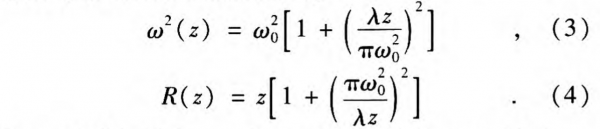
For a visible light,such as λ=587.6 nm with laser waist ω0 =1 mm, and z ≤ 1000 mm, because of λ/ω0² « 1, Eqs. 2-4 can be simplified as:
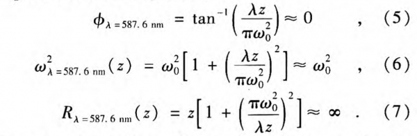
Equations 5-7 indicate that a visible laser can be described as a plane wave. Thus, it can be described as:
For a terahertz beam, for example λ1T =0.3 nm with laser waist ω0 =1 mm and z≤1000 mm, Eqs. 2-4 can only be simplified as:
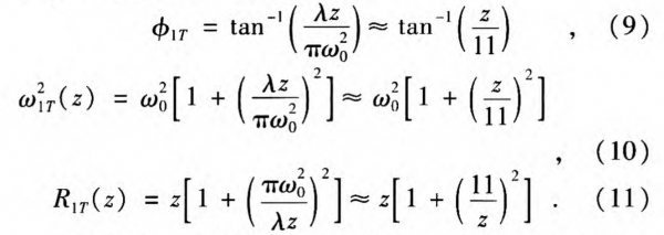
Equations 9-11 indicate that a terahertz beam described as Eq. 1 cannot be considered as a plane or spherical wave, which is quite different from the description of visible lasers.
For λ=500 nm and λ=0.3 mm,the ω(z) and R (z) depending on transmission distance z are shown in Figs.2 (a) and 2 (b), respectively. In Fig.2 (a), it is clear that the beam waist for the visible laser almost remains unchanged while the terahertz beam waist changes significantly along the z-axis with a large divergence angle of about 5.7°. A large divergence angle is not good for the free space transmission. From Fig. 2(b), we find that the spherical wave radius for the visible laser is thousands of times larger than its beam waist, which again proves that the visible laser can be described as a plane wave. However, for the terahertz beam, the spherical wave radius has the same order as its beam waist.
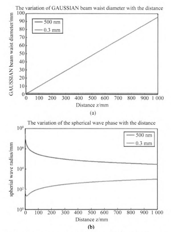
Fig.2 (a)The changes of the Gaussian beam waist diameter, (b)The changes of the spherical wave radius depending on the transmission distance z.
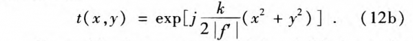
In Fourier optics, a lens can be used as a phase converter that can be described by

where t(x, y)is the phase conversion caused by the lens, f’ is the focal length of the lens, and k is the wave vector. For negative lenses, f’ < 0, Eq. (12a) can be rewritten as
If a positive lens was put behind a visible laser, for example λ=587.6 nm with ω0=1 mm, the field amplitude can be expressed as
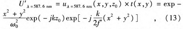
where z0 is the distance between laser and lens and can be measured easily. At position z0, exp( – jkz0 ) is a constant phase, so Eq.13 describes a convergent spherical wave. If the positive lens was replaced by a negative lens, a divergent spherical wave will be achieved.
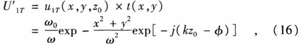
If a positive lens was put behind a terahertz laser, for example λ=0.3 nm with ω0 =1 mm,the expression for the field amplitude can be written as
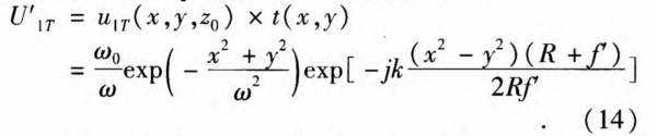
It means that a positive lens can also convert terahertz laser, but the convergent point is located behind the lens about Rf’/(R + f’) instead of at the focus.
If a negative lens was put behind a terahertz laser, for example λ=0.3 mm with ω0 =1 mm,the expression for the field amplitude can be described as
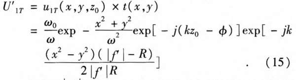
if R<|f’|, the negative lens make the beam divergent behind the lens.
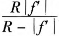
if R<|f’|, the negative lens focuses the beam behind the lens about
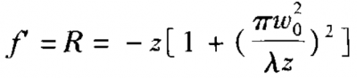
if R=|f’|, Eq. 15 can be simplified as
where
![]()
It means that when R=|f’|, the negative lens changes the Gaussian wave to a plane wave. So the key to achieving terahertz beam collimation is that the focus length of the negative lens should be equal to the spherical wave radius.
If Eq.17 is satisfied, we can convert the Gaussian wave into a plane wave. Before obtaining the parameters of the negative lens, it is necessary to calculate the parameters of the Gaussian wave carefully. A smaller spot helps to achieve a longer distance transmission, which indicates that the distance between the lens and laser waist should be as small as possible.
1.2 Gaussian Beams and ABCD Law
Consider a Gaussian beam passing through a thin lens and assume the focal length of lens as f’. According to the ABCD law of Gaussian beam propagation, the complex beam parameters have the relationship of
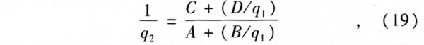
where q1 and q2 are the complex beam parameters of the Gaussian beam before and after the lens, respectively.
They can be calculated by
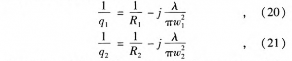
where R1, and R2 are the radiuses of the curvature of the equiphasic surfaces before and after the lens, w1 and w2 are the spot sizes before and after the lens. The matrix elements of a lens can be given by
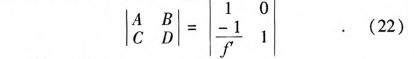
Then we can get
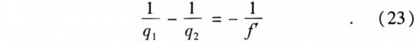
Substituting Eqs. 20~21 into Eq. 23 and separately equating the real and imaginary parts we can obtain the following relationships:
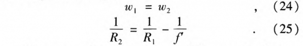
The lens makes the beam parallel, meaning that
![]()
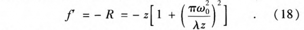
Based on Eqs. 25~26,we can get the parameter of the lens:
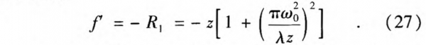
Equation 18 is just the same as Eq. 27, indicating that both the classical electro magnetic theory and ABCD laws prove that a negative lens can convert the Gaussian wave into a plane wave. The key to achieving terahertz beam collimation is that the foCUS length of the negative lens should be equal to the spherical wave radius.
Now consider a Gaussian beam, which has a spot size of w01 and a plane wave front, entering a lens with focal length f’. We then focus on calculating the beam waist position after the lens and its spot-size value w02. According to the ABCD law of Gaussian beam propagation, the transmission matrix for a lens with a focal length f’, followed by a free-space length z, can be given by:

The complex beam parameter q2 after the lens with a certain free-space length can again be calculated by Eq.19, where the A, B, C, D elements are shown in Eq.28 and (1/q1) is given by:
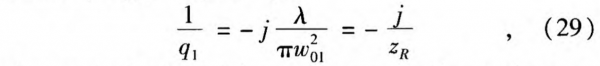
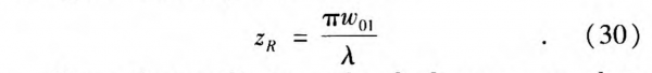
where zR is the Rayleigh range corresponding to the spot-size w01 and can be presented by:
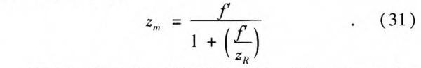
If now the coordinate zm after the lens corresponds to the position of the beam waist, according to Eq.(19), we can get zm by:
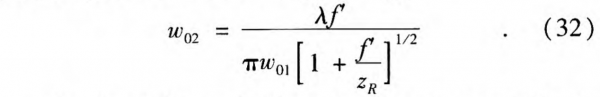
Substituting Eqs. 28~9 into Eq. 19 and equating the imaginary parts at the two sides of Eq. 19, we can get the spot size at the focal plane w02:
For the visible and infrared region, because of zR»f’, we can get zm≈f’. It is just the same as Eq. 13, meaning that the beam focuses at the focal distance f’. When zR»f’, we can simplify Eq.32 as:
For the terahertz region, zR and f’ are almost in the same order of magnitude, thus zm < f’. Therefore, we can see that the distance zm from the lens, at which the minimum spot size occurs, is always smaller than the focal distance f’. This is consistent with what Eq. 14 shows.
2. Experiment and Analysis
2.1 Design and Manufacture of the Terahertz lens
Lenses are always used in terahertz systems to improve the beam collimation and energy utilization ratio. Depending on the material, lenses used in terahertz systems are divided into two categories: high-resistivity silicon lenses and plastics lenses such as High Density Polyethylene (HDPE), Polytetrafluoroethylene (PTFE), and Picairn lenses. In our experiment, the lens is made of HDPE, whose transmissivity curve in the terahertz region is shown in Fig. 3.
Fig.3 Transmissivity curve of HDPE
From Fig. 3, it can be found that the transmissivity of HDPE depends on the frequency of the terahertz, which is caused by the characteristic of material itself. The detailed interaction mechanism between terahertz and HDPE is still not clear. However, this has little effect for the monochromatic light employed in our experiments.
In our experiments, the 1T terahertz emission is generated by pumping GaSe using a 1067.8 nm laser and a 1064 nm Nd:YAG laser from DFB. The terahertz beam has a beam waist of 3 mm. From Eqs. 3-4, we can calculate the spot diameter ω=4.3 mm and spherical radius R=188 mm at the distance z=100 mm. Based on Eq. 18, the focus length of the negative lens is calculated as f’= -188 mm.
2.2 Measurement and Analysis of the Divergence Angle
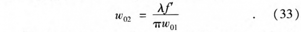
First, we measure the divergence angle without any lenses. A bolometer is used as the detector working under liquid helium condition. The signal value (unit: mv) can be read directly from an oscilloscope. The background radiation is tested as 4mv. Without any lens, signal is detectable only within 50 cm. Therefore, we measure the spot diameter at three positions z1 =10 cm, z2=20 cm and z3 = 30 cm. The measured results are shown in Fig.4. The beam width defined as the distance between the two points with the signal value of 1/e2 of the peak value. From Fig. 4, we can calculate the divergence angle of the terahertz source as 6°.
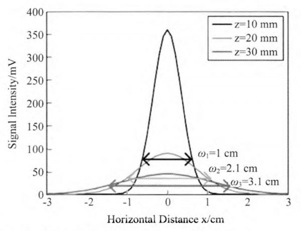
Fig.4 Measured results without any lenses
Secondly, we measure the divergence angle of tera-hertz beam after passing through a positive lens with a focal length of f’ =188 mm. The lens is positioned at z=188 mm behind the laser. A photo of the experimental system is shown in Fig. 5(a) and we measure the spot diameter at the places 1,2, and 3. The signal intensity distribution at each place is shown in Fig. 5(b). From Fig. 5(b), the divergence angle of the terahertz beam after the positive lens is calculated as 2.5°. Additionally, we found that the positive lens can convert the divergence beam, which is proved by the fact that there does always exist a position, about 100mm behind the lens, having the maximum signal value. The position is in good agreement with the theoretical value from Eq. 14.
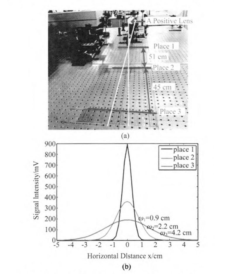
Fig.5 (a)Schematic of the experimental system and (b) the corresponding measured results when using a positive lens
Finally, we measure the divergence angle of tera-hertz beam passing through a negative lens, which has a focal length of f’ = -188 mm and its focus is located at z =100 mm. A photo of the experimental system is shown in Fig. 6(a). We measured the spot diameter at places 1, 2, and 3, which are the same as the places in positive lens experiments. The signal intensity distribution at each place is shown in Fig. 6(b). The divergence angle of the terahertz beam after the negative lens is calculated as 0.1°.
Fig.6 (a)Schematic of the experimental system and(b)The measured results when using a negative lens
Through the experiments, we can get the following conclusions:terahertz beams have a big divergence angle that is disadvantageous for the space transmission; though a positive lens with a large f-number can improve the energy utilization ratio, it has little improvement to the beam collimation; a negative lens can significantly improve the beam collimation, which is important for the space transmission, terahertz imaging, and so on.
2.3 Experiment of the Terahertz Beam Space Transmission
The space transmission distance, an important goal in our program, can be significantly improved when re-placing the positive lens with a suitable negative lens at the optimum position. Generally, to achieve a farther transmission distance, more positive lenses should be placed in the path. However, we can only achieve 20m transmission distance when using as many as nine positive lenses, as shown in Fig.7.
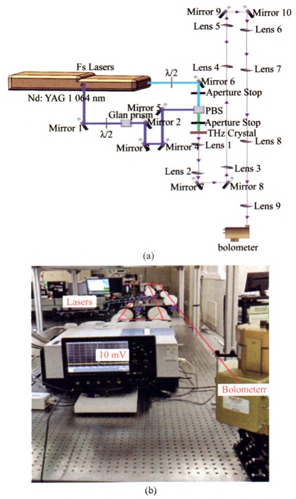
Fig.7 (a)Schematic diagram of the experimental system for 20 m terahertz transmission employing positive lenses and (b)Photo
Instead, using negative lenses as collimating lens, only three lenses are needed for the 20 m transmission distance, as shown in Fig.8. In Fig.8, the first lens, second lens, and the third lens are a negative lens with focus length of -188 mm, a positive length(9 m distance from the first lens) with focus length of 10 m, and a small positive lens with focus of 156 mm, respectively. Additionally, the signal collected in the latter scheme is seven times higher than that of the first. This result indicates that negative lenses in the path are advantageous for terahertz space transmission.
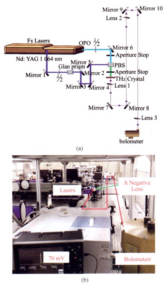
Fig.8 (a) Schematic diagram of the experimental system for 20 m terahertz transmission based on negative lens and (b) Photo
3. Discussion
It is well known that when the diameter of a lens is much bigger than the wavelength of light, we can use the geometrical optics, i.e. regarding light beam as a straight line, to analyze problems. However, the terahertz waves have a long wavelength, close to the diameter of an ordinary lens. Thus, geometrical optics is not applicable to the terahertz waves because of diffraction effect. Instead, the classical electromagnetic theory and ABCD laws can be used to design lens for terahertz trans-mission as shown in section 2. All the theoretical derivations support the following conclusions: firstly, a positive lens converges the terahertz beam in front of the focal plane instead of on the focal plane, which is quite different from the fact that it makes the visible or infrared lasers converge on the focal plate; secondly, although a negative lens can make the terahertz Gaussian beam divergence, convergence or parallel, how the beam performance behind the lens depend on the focus length of the negative length; thirdly, a negative lens which matches the radius of the Gaussian beam’s wave front is more appropriate for terahertz beam collimation.
The terahertz beams generated by the DFG are a kind of Gaussian beam with a big divergence angle, which is disadvantageous for the space transmission. Generally, three methods can be used to collimate the beam: a lens with big focus length, a beam expander, and a negative lens. However, in the first two methods, the big diameter of the parallel beam leads to a short transmission distance. Therefore, consequently, the negative lens is the best way to achieve the beam collimation and a longer transmission distance simultaneously.
Comparing the two schemes shown in Figs.7-8, we can summarize the disadvantages of the scheme in Fig.7 as following. Firstly, too many lenses are used. In Sect. 2, we have learned that the beam emitted from the terahertz crystal has a divergence angle up to 6 degree. At least two lenses are needed to realize laser beam collimation. If we put the first lens 10 cm distance behind the crystal, in order to get a collimating beam after the second lens with the divergence angle about 1 degree, the aperture of the second lens should be set as 6.3 cm.
Without taking atmospheric absorption into account, the spot size of the beam becomes 41.3 cm after 10 m propagation. It is too big for the weak power of terahertz laser. In order to reduce the atmospheric absorption, especially the water vapor absorption, the spot size should be as small as possible. So series of lenses should be used in Fig.7 to restrict the spot size. Secondly, as shown in Fig.3, the transmissivity of HDPE with the thickness about 2 mm for the 1 THz wave is about 0.85. Therefore, only 23 percent of energy is left when the beam passes through nine lenses as showed in Fig.7. This is the reason why the scheme in Fig.7 has a small SNR than that in Fig.8.
Based on the generation method, terahertz sources can be divided into two categories: the optical terahertz sources and electric terahertz sources. The optical methods consist of photoconductive antenna, optical rectification, air Plasmon, THz parametric sources, optically-pumped THz laser and semiconductor laser. The tera-hertz beams generated by the optical sources are Gaussian beams with big divergence angles. The theory pro-posed in this paper only applies to the optical terahertz sources. There are some differences for these optical THz sources in transmission efficiency. Accurate physical modeling for each optical terahertz source should be set up to calculate the transmission efficiency precisely. So, here, we just evaluate the transmission efficiency for each optical terahertz source roughly. Firstly, photoconductive antenna is a kind of omnidirectional antennas. The transmission efficiency for photoconductive antenna is much smaller than optically-pumped THz laser and semiconductor laser. Secondly, the fundamental principles for optical rectification, air Plasmon and THz parametric sources all are nonlinear optical effects. So the transmission efficiency for them has little difference with that for optically-pumped THz laser and semiconductor laser.
3. Discussion
Different with visible and infrared lasers, the wave front of terahertz beams cannot be simplified to a plane or spherical wave. It is a Gaussian beam with a big divergence angle which is disadvantageous for the space transmission. Though a positive lens with a large f-number can improve the energy utilization ratio, which is helpful for the space transmission, it can only slightly improve the beam collimation.
Both the theoretical derivations from the classical electromagnetic theory and ABCD laws show: firstly, a positive lens converges the terahertz beam in front of the focal plane instead of on the focal plane as visible or infrared lasers do; secondly, the positive lens used in front of the detector can improve the energy utilization without significantly enhancing the beam collimation; thirdly, the negative lens matching the radius of the Gaussian beam’s wave front is more appropriate for terahertz beam collimation. The parameter for negative lenses is determined by
where z is the distance from terahertz crystal to the lens, ω0 is the beam waist, and λ is the center wavelength of the terahertz beam. Experiments show that a negative lens with f’= – 188 mm at the match place, z= 188 mm, can improve the terahertz beam collimation from 6° to 0.1°, while a positive lens with f’=-188 mm at the optimum position, z=188 mm, which is determined by classical optic, only can converge beam at z’=100 mm with an angle of 2.5°. We realized 20-m terahertz space transmission with a negative lens in a very simple optical scheme. The signal obtained is seven times greater than that obtained with the positive lens scheme. The work shown in this paper will play an important role in free space transmission and terahertz imaging.