Laser for Surface Treatment
Surface treatment
The surface treatment techniques described are primarily used to enhance the wearresistance of the workpiece. Wear is defined as progressive material loss from the surface of a solid material, caused by contact and movement relative to a solid, liquid, or gaseous opposing material. Wear is a system-related property, and its science is referred to as tribology. The following tribological wear mechanisms are possible:
- abrasive wear; due to penetration of a soft surface by a hard body
- adhesive wear by micro-welding (cold set, scuffing, holes, scales)
- surface fatigue by exposure of the edge to cyclic stress loading causing minor or negligible plastic deformation (tongues, tears, tiny craters)
- tribochemical wear caused by chemical and mechanical interaction of the basic body and the opposing body with the surrounding medium (formation of reaction products as layers or particles)
Common surface treatment techniques may be distinguished into three main categories. Schemes and application possibilities of the most important techniques are shown briefly.
Wear resistance by laser radiation may be improved by the following material related alterations:
- Increasing the hardness
- Modifying the surface topography
- Applying wear-resistant coatings
- Inserting of internal compressive stresses
- Creating of reaction layers
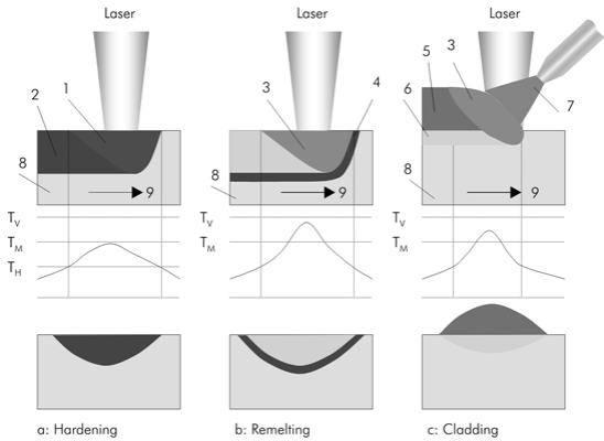
Surface hardening (a) is used exclusively for heat treatable ferrous products and is characterized by the fact that the process never reaches the melting temperature. Laser remelting (b) involves the creation of a remelting layer by heating the workpiece above the melting temperature. Thermochemical processes are based on heating while adding additional materials (solid, liquid, or gaseous ones). This includes laser alloying, laser coating and laser dispersing.
Edge layer hardening
The edge layer hardening technique maybe applied to steels with a sufficient carbon content (> 0.1 %) and cast iron including:
- unalloyed construction steels
- Tempered steels
- Tool steels
- Spring steels
- Roller bearing steels
- Case-hardening steels after carbonization
- Non-corrosive chromium steels
- Cast iron with laminar, spheroidal, and vermicular graphite with a sufficiently high carbon content in the matrix
The mechanisms in terms of material science correspond largely to those of conventional techniques (bath, furnace, flame, or induction hardening). It must be pointed out, however, that laser hardening eliminates the need for external quenching media (e.g. water or ice).
Edge layer hardening implies that the surface is heated up for a short time above austenizing temperature without melting it out. Good heat conduction to the component volume guarantees the required cooling rates (so-called self-quenching effect) in the hardness range in order to attain a martensitic structure with enhanced hardness.
Thus, a locally layer, defined by the laser beam width (perpendicular to the feed direction) with a hardening depth of up to 1 mm may be created. The temperature is determined by parameters of speed, spot size, average laser power, and the workpiece geometry. As a rule of thumb regarding the self-quenching effect, the cross-section of the component must be about ten times as long as the hardening depth.
In order to guarantee improved energy incoupling, absorbent coatings may be applied to the workpiece surface when CO2 lasers are used. No such coating is needed with the more short-wave Nd:YAG and diode lasers. The high-performance diode laser is particularly well suited for large-surface applications in surface treatment, due to its square beam, characterized by a ”top-hat“ intensity distribution in one beam direction (”slow-axis“) and a Gaussian profile in the other direction (”fastaxis“). Compared to other laser types, high-power diode lasers benefit from noticeably lower investment and operating costs achieved by high efficiency. In comparison to CO2 lasers there is higher absorption due to the short wavelength (808 nm and/or 940 nm) of the diode laser. These advantages make the high-performance diode laser an efficient, reliable and economical surface processing tool.
Major advantages of laser beam hardening as compared to conventional methods include:
- processing of hardly accessible spots
- localized hardening effect
- low distortion
- short processing times
- self-quenching effect
Edge layer remelting
Laser edge layer remelting, like laser hardening, is one of the thermal methods for surface treatment. By method, the component surface is briefly heated above the melting point, until a defined depth is reached. The melt then solidifies by selfquenching and re-crystallizes without major changes in the chemical composition.
This technique is primarily used for eutectic alloys, for hardening purposes, and corn-refinement. Remelting of cast iron to form wear-resistant ledeburitic edge layers may be mentioned as an example.
Laser alloying, dispersion and coating
Thermo-chemical processes are characterized by edge layer property changes i.e. melting and simultaneous adding of other materials. The following alternatives are distinguished:
- Solution alloying: the additional material is dissolved in the base material and largely remains in solution during solidification (for instance, gas alloying of titanium materials to create titanium nitride).
- Dispersion alloying: adding foreign particles that are only slightly dissolved (for instance, dispersion of diamonds).
- Coating: welding of filler materials by welding. The mixture is effected only in the transition zone and the properties of the layer material remain largely the same. The filler material may be fed either continuously in form of a wire or powder (one-step process), or it may be added in a two-step process; i.e., prior to laser treatment.
Due to the considerable impact of laser coating, the deposit welding technology is discussed in detail as follows.
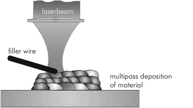
Deposit welding with filler material
The filler material is continuously fed to the laser beam, concentrated on the focal spot, where it is melted together with the base material. The material is added by a powder feeder through a nozzle oriented either coaxially or adjacent to the laser beam (pricking). With critical materials, this simultaneously affords an inert gas shield. Analog to conventional coating techniques (TIG, flame, plasma injection), a wide variety of powder coating materials may be employed, for instance:
- Pure metals (such as chromium)
- Copper alloys
- Aluminum alloys
- Nickel base alloys
- Cobalt base alloys (stellite)
- Iron base alloys (tool steels, non-corrosive steels)
- Hard metal alloys (WC-Co alloys).
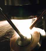
Increasingly popular beam sources today include Nd:YAG and high-power diode lasers, preferably in the kilowatt power range. Diode lasers, compared to CO2 lasers that were normally used in the past, attain higher speeds at simultaneously reduced power demand. Adding to these benefits is the noticeably enhanced process efficiency. The figure shows a valve being powder-cladded with a diode laser.
The power density spectrum typically ranges from 104 to 105 W/cm2 and, like the attainable maximum speed, depends largely on the volume to be melted down. Fine coatings with layer heights between 50 and 200 µm, for instance, can be realized at speeds of up to 100 mm/s (500 W, Nd:YAG laser or diode laser). Maximum layer thicknesses that may be achieved in one step are approximately 3 mm; greater thicknesses are created by repeated deposition of more layers.
Deposit welding with filler wire material
For many years, manual workstations using pulsed Nd:YAG lasers have held an important position, fine welding in the manufacture of jewelry and dental products.
Wherever small components with a complex geometry undergo local and precise processing, “manual” handling is decidedly superior to mechanical systems and serves to explain the considerable success of this machine concept.
A few years ago, the manual processing technology was adapted to much larger-sized components – based on experience gained in this market segment. Manual laser deposit welding with filler wire material has since gained significant acceptance in the tool and mold making industry.
Applications of local deposit welding can be found here on one hand to selectively increase the wear resistance of highly stressed areas of a workpiece. On the other hand, dimensional deviations or damage caused by production or use may necessitate the re-processing of a tool (such as metal forming, stamping tools or injection molds). Another possibility is a workpiece requiring considerable manufacturing effort. In small and medium-sized companies in particular, laser wire coating as repair or wear-protective technology contributes decisively to cost reduction in industrial production.
The flaw of a tool is filled using a laser beam and an application-related wire material, which is added separately.
The wire is passed over the component such that the laser beam melts the wire and the workpiece – surface together.
Depending on the used wire diameter, the total height is filled by repeated application of layers. Subsequent machining or electrical erosion techniques are used to shape the final geometry.
The advantage over conventional techniques such as electric arc or microplasm deposit welding are caused by higher heating and cooling rates as well as lower melting volumes.
This involves lower thermal stress of the base material as well as the risk of distortion, loss of cohesion and cracking. In addition, layer properties may be improved by creating fine grain sizes or by using additional materials with a higher melting temperature. In terms of manufacturing technology, more precise structures may be attained with laser technology, as filler wires with a diameter as small as 100 µm may be processed.