Laser for Marking
Laser marking normally includes vector and mask technology as well as dot-matrix printing. With the vector technique, which holds the larger market share today, the laser radiation is guided via two revolving mirrors. The mirror axes are oriented perpendicularly to each other, so that one mirror sends the beam in x direction while the other one deflects it in y direction. Any given point in the field below, whose size depends on the focal distance of the focusing lens, may be targeted by rotation of these mirrors. Any conceivable contour may be created if the mirror movement is now combined with activation (marking) and deactivation (jump, for instance between letters) of the laser beam by Q-switch operation. Deflection as well as activation and deactivation are controlled by a commercially available computer with a special laser printing software. After deviating the beam via the mirrors, it is focused on the workpiece and positioned underneath the deflection equipment by using a planar field optical system. The laser beam is therefore passed over the image to be printed, following the prescribed path.
Even the standard control software for universal marking systems offers a host of possibilities to produce printed texts and graphics. Graphical elements created by other programs (such as CAD), or free-hand sketches scanned and then vectorized, may also be used as a basis for vector marking. In addition, direct printing of bitmaps is possible. The excellent geometric flexibility has certainly helped to make this the most popular marking solution today.
The rotational speed of the mirrors may be adjusted so as to directly control the marking speed and thus the path energy, which has a strong influence on the printing result.
Since the mirror rotating drive is a galvanometric one, the mirrors are referred to as “Galvo mirrors” and the complete unit containing the mirror and the lens is a socalled “galvo head”. Coupling via optical fibers is possible under certain conditions.
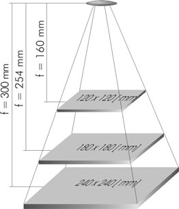
The sizes of the marking fields depend on the focal distance of the installed planar field optics. The planar field optical system, also referred to as a focusing lens, is a special lens imaging the focal point in a planar printing plane (a marking field). At a focal distance of, for instance, f=160 mm, the field to be marked has a size of 120×120 mm resp. ∅150 mm.
Other alternatives are f=254 mm, 180x180mm (∅230 mm) or f=300 mm, 240×240 mm (∅270 mm) (see Figure below). The focus diameter, which arises from the focal distance, influences the printing result and should be verified for the application in question.
If, for special applications, a marking field is needed that is larger than the standard one with its usual focal distance, then a double-head system may be used for marking. A beam source is equipped with two adjacent marking heads (double head).
These heads may either perform two identical markings simultaneously (beam splitting), or they may mark one after the other (beam switching).
In mask technology, the negative of a character or a set of characters is illuminated by a correspondingly expanded laser beam and is then projected onto the workpiece.
Imaging of complete characters may be associated with high printing speeds. In addition, systems are available that can project and position a variety of characters onto a fixed workpiece, using appropriate mirror optics. However, due to lack of flexibility of this beam shaping technique , its market significance is now declining.
In dot-matrix printing, the lines/vectors are replaced by individual dots. Thus, complete characters are generated by a defined number of laser shots. A 5×7 matrix is created, for instance, if the imaged character is to be 5 dots wide and 7 dots high.
Thus, logos, characters, or entire texts may be projected onto the desired surface.
This technique is commonly used for parts in the packaging industry that are moved during marking, or for cable marking.