Laser for Beam Delivery
The beam delivery system is used to guide the laser beam from the source to the processing spot with as little loss as possible and without affecting the beam quality.
In CO2 lasers, the beam is typically guided via beam bending mirrors. Due to its wavelength, the radiation of solid-state and diode lasers may be transmitted and shaped by glass optics, making it possible to use optical fibers for this purpose. In the presence of high power densities, the beam delivery components are equipped with a suitable cooling device.
Mirror beam delivery
In conjunction with CO2 lasers, bending mirrors are used as a basis for beam delivery systems. Mirrors, with high reflectivity as well as sufficiently high surface precision (deviations < λ/20), combined with precise mechanical guiding systems create the necessary conditions for a constant beam quality throughout the processing envelope. Due to their favorable heat dissipation properties, pure copper mirrors (99 % reflectivity) are often used; although coated metal mirrors are gaining importance also.
Two-dimensional laser beam movements are commonly effected by fast-moving optical systems, ”flying optics“, that are characterized by high beam transmission quality in combination with high translational acceleration and speed. Various mirror arrangements for three-dimensional beam movement as well as three-dimensional mirror beam guides have gained a position in the industrial market. These special articulated-arm laser beam delivery systems do not need to be adjusted and allow processing in a working range of up to 5 m. These are available in a lightweight design with carbon fiber-reinforced plastic pipes.
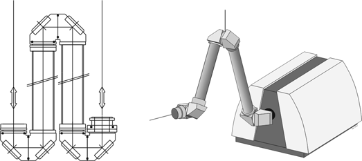
Articulated-arm beam delivery systems may be utilized in combination with industrial robots as well as with CNC systems. This beam delivery concept has a major advantage over conventional beam delivery systems, in that it requires very minor adjustments. Additionally, the constant length of the optical path makes it possible to implement focusing optics with a constant beam diameter. This design eliminates the need for intricate systems (see beam telescopes) to compensate beam diameter variation over the length of the beam delivery system, caused by the beam divergence. Using rigid, lightweight glass or carbon fiber-reinforced protective pipes makes it possible to create a lightweight construction based on this beam delivery concept.
Optical fiber beam delivery systems
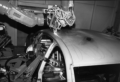
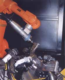
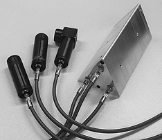
The wavelength of the laser radiation of solid-state lasers and diode lasers makes it possible to use highly flexible optical fibers for beam delivery (Figure below). Optical fibers may be used to transmit the laser beam to areas that are inaccessible for rigid beam delivery techniques, such as the interior of car bodies. Optical fibers, like electrical cables, are laid from the laser to the workpiece. At regular intervals along the line, strain-relief devices are installed between the laser source and the robot to prevent fiber wear. This can be caused by mechanical stress that may arise from the highly dynamic robot movements. When laying the fiber-optic cable, it is important to ensure that a minimum bending radius is maintained.
Unlike the divergent beam delivery systems of gas lasers, the core diameter of an optical fiber limits the beam diameter of the solid-state laser or diode laser over the entire beam delivery distance. Optical fibers may be used to achieve very long transmission distances. The laser beam exiting from the fiber, after all, is subject to the known beam propagation laws of a rotational symmetrical laser beam. The beam divergence, however, is limited by the numerical aperture of the optical fiber and depends especially on the incoupling conditions at the fiber input. This means that the beam quality is compromised slightly by passing through an optical fiber beam delivery system. Laser radiation inside an optical fiber is transmitted almost entirely without loss. It is only during input and output coupling that more power loss occurs if uncoated fiber ends are used.
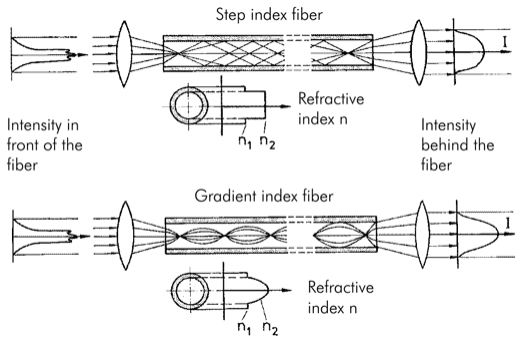
Optical fibers consist of a quartz core, surrounded by a quartz jacket with a lower refractive index. There are two types of optical fibers: step-index fibers and gradientindex fibers. With gradient-index fibers, the refractive index decreases parabolically toward the outer surface. With step-index fibers, the refractive properties change incrementally between the quartz core and the jacket. Inside the fiber, the light is guided by total reflection at the interface (Figure below). The difference between the refractive indices of the core and the jacket determines the acceptance angle of the fiber; i.e., the maximum angle of divergence θmax at which total reflection is still observed. This fiber property is characterized by the numerical aperture NA, quantified by NA = sinθmax.
As protection against mechanical damage, the fiber is embedded in a kevlar-reinforced plastic tube, which in turn, is surrounded by a helical metal tube. This concept results in a robust, flexible fiber. The latest generation of fibers developed by ROFIN is equipped with an additional data cable that may be used for signal transmission between the laser and the machining head. Today, optical fibers with a core diameter between 0.15 mm and 1.5 mm are used for industrial material processing. With ROFIN solid-state lasers, up to 6 optical fibers may be utilized in a laser system.
Combined with beam switching for multiple optical fiber outputs, laser utilization rates may be considerably enhanced with the combination of a large number of working stations or robots. This added flexibility allows a variety of system concepts to be developed. Beam switches may be built in accordance with the customer’s requirements. The power may be alternately sent down separate fibers or may be split by 50 % for parallel operation of two fibers.
Beam telescopes
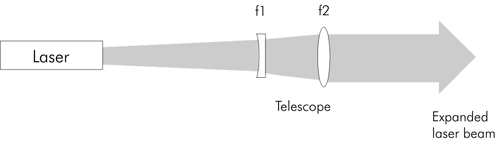
Telescopes may be used to expand the crude beam created by the laser. This concept is based on the physical principle that a freely propagating laser beam is expanded by a lens and then collimated. The product of the beam radius and the divergence (half-angle) is constant along the entire optical path. A beam delivery system can
therefore cover long distances by initially expanding the beam diameter and reducing the angle of divergence. This makes it possible to compensate for any effects resulting from a varying optical path length or from the different operating conditions of the beam source. Figure below shows the typical telescope design that is used for beam expansion in CO2 and Nd:YAG lasers.
Beam splitting
It may be desirable to simultaneously use the power of a beam source at several positions (energy sharing). Alternatively, the beam power may be made sequentially available at different processing stations (time sharing). For this purpose, standard components for CO2, Nd:YAG, and diode lasers are available today, based on different principles.
In the area of fine welding with pulsed lasers for the manufacture of electrical, electromechanical, or optoelectronic components, the laser beam may be coupled into as many as 9 fibers. One laser can therefore be used to serve several working stations.
In order to achieve a balanced thermal distortion during welding, the workpiece may be subjected to simultaneous processing with 3 fibers, arranged at 120° angles (energy sharing). At most, this may require a total of 9 fiber couplings for 3 working stations with 3 fibers each.