Laser for Beam Shaping
Having discussed beam delivery components, beam-shaping components will now be considered. Beam shaping components, as a rule, are integrated into the machining head, so the laser beam is projected onto the workpiece. The initial values needed to design a beam projection include the beam waist diameter in front of the first beam shaping optics, and the required beam diameter on the workpiece. The size of the beam on the workpiece is an important process parameter, but solely depends on the application.
Focusing and optical beam shaping
For material processing, the energy density on the workpiece is adapted to the required manufacturing task. In most cases, the laser radiation must be focused on the workpiece to achieve the required energy density. The required focus diameter and the Rayleigh distances on the workpiece are attained either by adjusting the focal distance or by corresponding adaptation of the beam diameter at the position of the focusing optics.
Transmitting optical systems (such as lenses) or reflecting optical systems (such as mirrors) may be used as focusing elements.
ZnSe (zinc selenide) is the main material used in focusing lenses for CO2 lasers. It has excellent transmission properties for the CO2 laser wavelength and favorable heat dissipation characteristics. For this reason, ZnSe focusing optics, equipped with anti-reflection coatings on the beam inlet and the beam outlet side, are utilized for most CO2 laser cutting applications. Mirrors for CO2 lasers consist of copper, which is easily cooled with water and, if appropriately coated, exhibits maximum reflectivity (dielectric coating). This coating canalso offer good protection against mechanical damage (molybdenum). Such mirrors are used in industrial lasers at a power of up to 20 kW. Quartz optics may be used for beam shaping in solid-state and diode lasers. Suitable coatings give rise to transmitting (anti-reflection coatings) as well as reflective properties that are tuned to precisely defined radiation wavelengths.
In many cases, the machining head should make it possible to adjust the beam waist, the diameter of which is defined for material processing, relative to the workpiece surface, along the beam incident axis. This is achieved by shifting the focusing optics in the beam direction. To make sure that the defined processing beam diameter remains unchanged, the beam diameter on the focusing optics must remain as constant as possible. This is achieved by using the above-mentioned beam telescopes that generate an incident laser beam on the focusing optics with very little divergence.
With fiber delivered, solid-state or diode lasers, a combination of fiber emerging surface, exiting angle, and downstream collimation optics, define the requirements for a beam telescope. The collimation optics, just like the focusing optics, are integrated into the machining head and shape the laser beam emerging from the fiber to create an almost parallel beam with a defined diameter. The combination of collimation and focusing optics represents the simplest array of beam shaping optics inside a machining head. The minimum beam diameter needed for processing may be approximated on the basis of the focal distances of the beam shaping optics and the laser beam waist diameter before it reaches the beam shaping optics (this corresponds either to the beam waist diameter of the laser beam during output coupling from the resonator or the fiber core diameter).
The presence of a collimated beam inside the machining head offers many more ways to manipulate the laser beam for processing. The almost perfectly parallel beam, for instance, may be deflected by a mirror, which considerably shortens the length of the machining head. Bending mirrors may also be equipped with special coatings, making it possible to integrate a viewing camera or a sensor system into the machining head to supervise the process. Likewise, special-purpose optical systems may be installed in the optical path between the collimating and focusing optics.
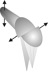
Optionally, optical systems splitting the laser beam may be installed. These systems usually generate two separate beams with different beam diameters that are available for material processing. The distances between the beam diameters and the energy distribution of the laser beam over the individual beam diameters depend on the design of the specialized optical system. Such optical systems are referred to as double-spot or variospot optics.
The vario-spot optics, shown in Figure below, for example, may be used to enlarge the seam width according to the preset gap between the focal points, also increasing the tolerance for bridging gaps or faulty positioning of the laser. In addition, this system enhances the process stability during aluminum welding and may be used to suppress the humping effect.
A similar effect may be achieved with scanner systems or optical systems with mirror facets for beam homogenization. Since scanner mirrors, due to their stringent dynamic requirements, are designed to be as small and as lightweight as possible, these systems are frequently utilized in the focused area of the laser beam. Since laser material processing is a thermal manufacturing technique, which means the material states may change, processing can give rise to fumes or even metal spatter. To protect the focusing optics from this debris, protective windows made of quartz material are incorporated between the focusing optics and the workpiece in solid-state lasers and diode lasers. The protective windows can be monitored by integrated sensors to allow monitoring of the degree of contamination of the protective windows. This avoids unnecessary maintenance of the protection glass.
Since laser material processing is a thermal manufacturing technique, which means the material states may change, processing can give rise to fumes or even metal spatter. To protect the focusing optics from this debris, protective windows made of quartz material are incorporated between the focusing optics and the workpiece in solid-state lasers and diode lasers. The protective windows can be monitored by integrated sensors to allow monitoring of the degree of contamination of the protective windows. This avoids unnecessary maintenance of the protection glass.
Process adaptors
Process gases are required for many laser material processing techniques. These gases, for most applications, are added via suitable nozzles near the point of interaction between the laser beam and the workpiece. In fusion cutting of metals and non-metals, the process gas is needed to eject the molten material produced by the laser beam from the open cut and to supply the interaction zone with active gas. In sublimation cutting, the process gas is used to enhance steam ejection and simultaneously protect the focusing lens. In the case of welding, process gas is used for a two-fold purpose. On the one hand, it serves as an inert shielding gas for the melt – a well-known and necessary procedure in classical welding. On the other hand, it is needed to stabilize the metal vapor and the plasma released from the keyhole, especially in conjunction with CO2 laser welding. Some welding techniques, however, do not require inert gas shielding of the molten material. For example, due to the short wavelengths of Nd:YAG and diodes lasers, the need for inert gas is eliminated. Special welding gases are available to optimize the processing of zinc-coated sheet metal and aluminum. Due to the inert and active components, these gases guarantee optimum plasma control and have a positive influence on the weld pool.
The following section describes the most common nozzle configurations for welding and cutting purposes.
Welding nozzle configurations
For most welding applications, the most effective configuration is a lateral arrangement at a 30° to 45° angle to the optics, with a diameter ranging from 3 to 8 mm. Flow rates are typically between 8 and 20 l/min. The welding result is relatively independent of the direction, which makes it possible to weld circular shapes with this array. Coaxial nozzles are available for tasks requiring full directional independence. An example is the welding of plate heat exchangers.
The types of inert gas used for welding include helium, argon, CO2, and nitrogen, as well as mixtures of these gases.
Various cross-jet nozzle designs have been developed to protect the welding optics from the fume and metal spatter that accompanies many welding applications.
Most of the solutions are based on the principle of an air-flow oriented perpendicularly to (across) the laser beam.
Cutting nozzle configurations
The process gas nozzle is even more important for cutting than for welding. Only concentric nozzles are used for the various cutting processes. The geometry of cutting nozzle tips is characterized by a conical internal contour, ending in a cylindrical outlet aperture. Favorable flow conditions are ensured by a ratio of > 1 between the length of the cylindrical section and the diameter of the aperture, as long as the beam profile permits this.
Nozzle aperture diameters are typically in the range between 0.8 and 3.0 mm.
For high-pressure cutting with an inert gas (N2), pressures are usually between 3 and 25 bar. The distance between the nozzle and the workpiece surface is usually set to a value between 0.5 and 1.5 mm. For flame cutting with oxygen, the process gas is pressurized to a value between 0.5 and 10 bar. The cutting gas pressure, which considerably influences the cut quality, should be as constant as possible (with a tolerance of up to +/- 10 %).
Sensors and process monitoring
Due to the tolerances exhibited by actual components and the inherent imprecision of the overall system or the part processing programs, many applications require a positional correction of the cutting head relative to the pre-programmed contour. Based on different sensor concepts, a variety of position control and adjustment systems have been developed. The following text provides an overview of the systems that are used in manufacturing industry today.
Distance sensors
Systems for controlling the distance along the z-axis are often used in conjunction with cutting applications to maintain the constant distance required between the tip of the cutting nozzle and the workpiece surface. There are non-contact systems determining the distance by capacitance as well as mechanical (tactile) systems. In addition, other concepts (optical, inductive, or acoustic ones) are also possible, yet these approaches have not had any impact on industrial manufacturing. Conversion of the distance signal is preferably via a highly dynamic additional axis moving the machining head within the range of control. In industrial applications, the most common systems used are based on capacitive distance sensors to measure the actual distance. In this concept, the sensor determines the electrical capacitance, which depends on the distance between the nozzle tip and the workpiece surface. Various cutting optics or cutting nozzles for standard focusing optics are now available.
Tactile systems are utilized primarily to process non-conducting materials such as plastics or wood, for which capacitive systems are unsuitable. In these systems, the actual distance is determined by a probe that is in contact with the workpiece surface. In many cases, this probe is arranged concentrically around the cutting nozzle, in a circular array. In addition, tactile systems, such as pressure-fingers or padrollers, are also used for welding in conjunction with three-dimensional processing to reduce the gap between the parts to be joined, thus maintaining the distance between the workpiece and the machining head.
Seam tracking sensors
The required energy densities needed to melt the material in association with laser beam welding, especially deep penetration welding, necessitate stringent requirements regarding the total tolerance of the parts to be joined. Welding gives rise to positional tolerances arising from the tolerances of the clamping technique, the component tolerance (particularly deep drawn or pressed components), the tolerance associated with seam preparation, and contour path tolerances introduced by the beam guiding device. The total tolerances are usually measured by tactile or laser triangulation sensors. In the tactile sensor concept, the translational movement is recorded in a continuous scan by a mechanical probe. Two additionally integrated axes correct any path deviations. Tactile sensors have the essential advantage that their operation is not impaired by dirt and welding fume that may cause problems with optical sensors.
To monitor a seam with a laser triangulation sensor, laser light is first projected onto the surface. A CCD camera then analyses the laser line on the surface and transmits the image to an image processor. On the basis of this data, the image processor determines the workpiece profile. The sensor computer then calculates the necessary positioning and motion of the welding head and the required parameter adjustments, and then transmits this information to the movement system. This sensor technology may also be used to measure surfaces or to verify certain dimensions.
Process monitoring
Process monitoring primarily includes the processing of optical and thermal signals received from the machining process, primarily for quality analysis. If welding gives rise to any weld defects (like blow holes, for example), this information appears as a disturbance in the UV or IR signal of the back-reflected light. This comparative check aids the decision about whether or not a given component should be rejected for non-conformance.