Laser for Separating Functions
Laser separation techniques include cutting, drilling, material removal and marking by ablation (engraving). This chapter provides a description of the cutting, drilling, and ablation processes. The marking techniques in this context are to be discussed in a separate section, together with other marking techniques
Cutting
In conjunction with separation by laser radiation, three different processes can be identified, depending on the process gas and the energy supply: flame cutting, fusion cutting, and sublimation cutting.
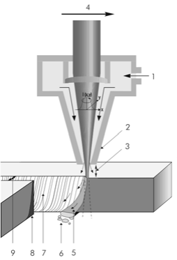
Basically, metal laser cutting is effected by locally heating the material at the focal point of the focused laser beam above its melting point. The resulting molten material is ejected by a gas flow oriented coaxially to the laser beam, so that an open cut is formed.
 |
 |
For low-alloyed steels in particular, oxygen is typically used as a cutting gas. This process, referred to as laser flame cutting, receives additional energy from the exothermic reaction of the material which is heated above the ignition temperature.
Thus, less laser power is required in this case than for laser fusion cutting. Today, laser flame cutting is industrially used up to 40 mm material thickness; it should be noted, however, that an appropriate width of cut is needed for the ejection of the smelt as the material thickness increases.
In the case of higher-alloyed steels and aluminum, an inert gas (nitrogen, argon) is typically used as a cutting gas. This process, referred to as laser fusion cutting, is effected solely by the energy of the laser beam. The required laser power is therefore higher than that for laser flame cutting.
Laser fusion cutting affords non-oxidized cut edges, which is particularly important when welding is the next process step after cutting. Today, laser fusion cutting is used industrially for materials up to 25 mm thick.
A comparison of these two techniques shows noticeable differences regarding the process characteristics. By exploiting exothermic energy, flame cutting attains cutting speeds that are approximately twice as high as in fusion cutting – at a comparable average laser power. The required gas pressure for flame cutting, too, is lower (typically 0.5 to 6 bar; while in fusion cutting it is 8 to 20 bar). This is due to the difference in ejection characteristics of the molten material. This also explains why the maximum sheet metal thicknesses that can still be fusion cut are noticeably thinner than those that lend themselves to flame cutting.
Primarily, CW and pulsed solid-state lasers as well as CO2 lasers in the power range of several watts (micro-cutting) up to 10 kilowatts are used for these applications. The selection of a suitable beam source depends largely on the cutting geometry, the cycle time, the system technology, and, in particular, the material itself.
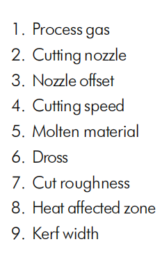
In sublimation cutting the material is molten by the absorbed laser energy until it partially evaporates. Since the resulting steam is pressurized, material removal is effected by ejection from the open cut against the beam impact direction.
This requires noticeably higher power densities in material processing and is simultaneously associated with much slower speeds than the two previously described laser cutting techniques. Since the cutting depth in one pass (single pass) is frequently only in the range of several microns, thicker materials are separated by the so-called multipass method.
Typically, cross-sections that can be cut by an economically feasible process are approximately no larger than 1 millimeter, depending on the material. The lasers used for these purposes are normally Q-switched Nd:YAG lasers for metals, ceramics or diamond. CO2 lasers are employed for ceramics and plastics. The power range, at 1 to 300 W, is noticeably below the power of the two previously described techniques.
In sublimation cutting, a process gas is used to create a protective atmosphere or a shield. The term “sublimation cutting” may be misleading. Pure metals are evidently unable to undergo sublimation; i.e., direct transition from the solid state to the gaseous state. Ablation is always effected in the sequence heating – melting – evaporation. However, it is possible that metals (such as tungsten or molybdenum) and nonmetallic elements (such as silicon) form sublimating reaction products with the ambient air during laser material processing.
The quality of a laser-cut component may be assessed, among others, according to the following criteria:
- Roughness (DIN 4768)
- Corrugation
- Quality of cut edge (DIN 2310: drag-line depth; casting; unevenness; drag-line trailing
- Cutting width, conicity
- Reaction layers
- Structural transformation
- Heat input
- Cutting speed
Drilling
Ablation in laser beam drilling is to be considered physical removal; i.e., the external gas support only serves to protect the material processing optics from the material ejected in beam direction. And involves evaporation-induced melt displacement. Pulsed laser radiation is almost exclusively used for this purpose, since the ablation limit for metals is typically at power densities of approximately 5.10~7 W/cm².
In terms of process technology, four different types of laser beam drilling may be distinguished: single-pulse drilling, percussion drilling, trepan drilling, and twist drilling. In single-pulse drilling, the hole is created by a single laser pulse. Since the drilling depth depends mainly on the pulse duration, attainable single-pulse drilling depths are between several micrometers for ns pulses and several millimeters for ms pulses. To achieve greater drilling depths, repeated irradiation of the same material processing position is needed. This procedure is referred to as percussion drilling. To drill diameters exceeding the laser spot diameter or deviating from the generally circular geometry, the laser beam and the workpiece are moved relative to each other. This is referred to as trepan drilling; it involves moving the component, the focusing lens, or one or more deflecting mirrors (piezo-controlled mirror, galvanometer scanner).
Twist drilling is a special version of trepan drilling. In this case, in addition to the xy circular motion, the focus position is shifted inside the workpiece, describing a helical path.
By choosing laser radiation with a suitable wavelength and power density is used, practically all solid materials (metals, semiconductors, polymers, ceramics, diamond, paper) can be drilled.
Laser precision drilling, however, implies one restraint: given maximum precision requirements in metallic materials (such as automotive fuel injectors), there are still certain limitations to be considered regarding minimum concentricity and burring, especially as compared to electroeroded or mechanically manufactured through holes.
Ablation, Scribing, Structuring
For most industrial laser applications for ablating material processing pulsed laser radiation is used as only the high-power density that is required for ablation can be achieved in this way. Material ablation with continuous laser radiation (laser machining, chemically supported ablation), has not yet been launched in the industrial context due to the very low ablation rates.
A certain vapor pressure is created by brief laser pulses with high-power density; this pressure is sufficient to radially expel the melt film as a side product.
Applications for laser ablation may be classified in accordance with the dimensionality of ablation; i.e., the overlap directions of individual laser pulses.
If each individual laser pulse forms a separate ablation area, this is referred to as 0- dimensional ablation. Such processes are used for single-pulse structuring, to improve adhesive surfaces, and to create a micro-pressure chamber system in lubricated surfaces.
One-dimensional ablation is given when laser pulses overlap in one direction. This occurs, for instance, with line-shaped ablation of thin layers (solar technology, TFT screens), surface scribing (laser honing, isolating of ceramics substrates), and percussion drilling.
If the laser beam overlaps in two spatial directions, this is referred to as two dimensional ablation. It includes the surface ablation of workpiece surfaces, for instance by single scanning a line-filled contour for marking purposes. The same principle also applies to the separation of workpieces with thicker cross-sections by repeated passing of the same contour.
With regard to volume ablation on components, a distinction is made between 2 ½ and 3-dimensional ablation. 2 ½-dimensional ablation is given with repeated passing of a surface contour, as it can also be noted in deep marking or trimming. This results in smooth bottom surfaces and walls with a process-related taper, which depends on the pre-set laser parameters and the material in question. In some industrial applications, however, depth-related information is also processed, such as walls with a given conicity, or any topographies of the ablationed ground. The latter example is referred to as 3-dimensional ablation and is increasingly used in production of filigree injection molds or embossing dies.