Irradiance characteristics for the off-axis parabolic collimating mirror
irradiance analysis; collimator; off-axis parabolic mirror; radiation transfer model; ray tracing
Abstract
Off-axis parabolic mirror has been widely used in sensor calibration, radiation measurement, infrared target simulation system and so on, because it takes many advantages such as no chromatic-aberration, common used material, broadband, no center block. The irradiance characteristic of the off-axis parabolic collimating mirror was evaluated by both theoretical analysis and simulation study. Both the expression for the irradiance distribution on the exit pupil plane of the off-axis parabolic collimator and the relations between the angle of divergence and the parameters of the collimator such as the focal length of the mirror, the aperture size of the source and the angle of of axis, were theoretically derived based on the radiation transfer model. The irradiance distribution on the exit pupil plane of the collimator was simulated by ray tracing method. The uniformity of the distribution was also analyzed. The method proposed here is useful to increase the collimation and uniformity of the off-axis parabolic mirror.
Introduction
The collimating optical system is widely used in the development of infrared target simulators and radiation calibration systems. It is a comprehensive optical detection basic equipment. The collimating optical system is generally composed of a reference radiation source, a collimating mirror and related mechanical structures. For the collimation system working in the mid- and far-infrared band, the black body is generally used as the radiation source, and the collimating mirror is generally a reflective optical system. The collimating optical system based on the off-axis parabolic mirror has attracted people’s attention because of its advantages such as no central occlusion, no chromatic aberration, easy availability of materials, high utilization rate of light energy, wide working spectrum, foldable optical path, and relatively compact structure.
As the collimating optical system based on off-axis parabolic mirror becomes more and more widely used, in the process of developing the collimating system, evaluating the performance of the collimating system under ideal conditions and determining the influence of its system parameters on the performance of the collimating system have an impact on the performance of the system. Development has a positive meaning.
The evaluation indicators of the collimating optical system mainly include the output irradiance, uniformity and collimation; the system parameters mainly include the aperture of the black body diaphragm (ie the diameter of the light source), the focal length of the parabolic mirror, and the off-axis angle.
The existing literature uses the analysis method of the vector equation to trace the space rays of the parabolic mirror, and simulates and analyzes the influence of the off-axis parameters and other parameters on the divergence angle of the collimated beam. For the irradiance output of the collimation system based on parabolic mirrors, there are few reports in the literature. The traditional performance analysis mainly focuses on the analysis of image quality, MTF and so on.
In this paper, based on the irradiance transfer model, the irradiance distribution and collimation at the exit pupil of the off-axis parabolic collimation optical system are theoretically analyzed, and the corresponding calculation expressions are derived, which provides guidance for the selection of system parameters.
Then use ZEMAX software for ray tracing, conduct a comprehensive simulation analysis on the collimation and irradiance output and verify the theoretical analysis, and give the two-dimensional distribution of irradiance at the exit pupil of the collimation system and Uniformity size value.
1 Off-axis parabolic output irradiance characteristic analysis model
As shown in Figure 1, it is assumed that the collimating optical system consists of a surface radiation source with a Lambertian circular aperture and an off-axis parabolic mirror (OAPM). The radiance of the radiation source is Ls, the radius of the light source is rs, and the area is As; the diameter of the off-axis parabolic mirror is d, the focal length is f, the reflectivity is ρ, and the off-axis angle is φ. The center of the light source coincides with the focal point of the off-axis parabolic mirror, and the normal at the center of the light source coincides with the line connecting the center of the parabolic mirror and the focal point. The receiving surface is set directly in front of the center of the off-axis parabolic mirror, that is, the exit pupil plane.
Ideally, a light spot centered on the intersection of the centerline and the receiving surface will be formed on the receiving surface.
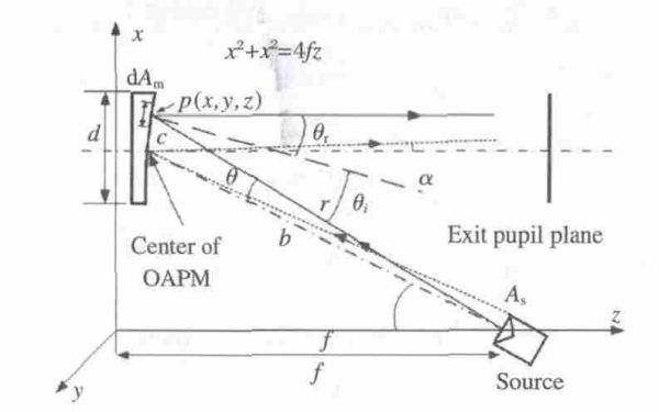
Fig.1 Schematic of off-axis parabolic mirror for the analysis of irradiance characteristic
From the irradiance transfer model, it can be known that the irradiance formed by the surface light source and the surface at a distance r can be analyzed in Figure 2. In the figure, dAs represents the primary luminous area of the light source, and the irradiance formed on the plane with a distance of r and an area of dA is E, then we have

Where:
Ls is the radiance of the light source;
θ1 and θ2 are the angle between the normal of the emitting surface dAs and the illuminated surface dA and the r direction, respectively.
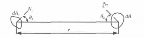
Fig.2 Schematic for the analysis of irradiance of an area source with distance of r
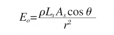
According to the above-mentioned principle of irradiance transmission and the corresponding geometric relationship, the irradiance distribution of the light emitted by the central region dAs of the light source on the off-axis paraboloid can be deduced. From above equation E, it can be known that the irradiance of the micro-surface element dAm corresponding to any point p of the light source on the parabolic mirror surface is:

In the formula:
Ls is the radiance of the light source;
θ is the angle between the incident light and the line connecting the center of the light source to the center of the parabolic mirror;
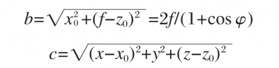
r is the distance from the center of the light source to any point p on the off-axis parabolic mirror, and the coordinates of p point are (x, y, z), and satisfy the paraboloid equation x2+y2=4fz; θi is the incident angle. According to geometric principles, the expressions of r and cos θ are as follows:
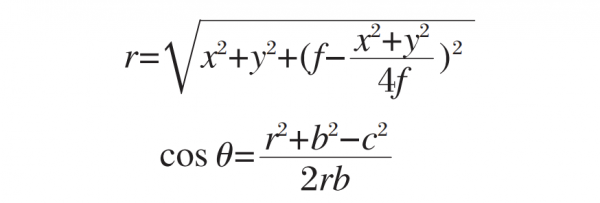
In the formula:
b is the distance from the center of the light source to the center of the off-axis paraboloid mirror;
c is the distance from the incident point p to the center point of the off-axis paraboloid mirror.
Let the coordinates of the center point of the off-axis paraboloid be (xo, 0, zo), from the geometric relationship, we can get:
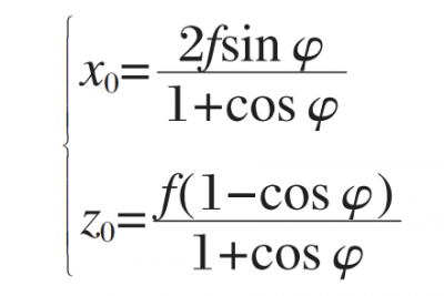
Similarly, the expressions of b and c can be written as:
Then the irradiance of the outgoing light reflected by the dAm region on the paraboloid is:

Since the angle of incidence is equal to the angle of emission, that is, θi=θr. Therefore, the irradiance of the outgoing light can be written as:
Putting equations of the expressions of r, cos θ, b and c into equation above, we have:
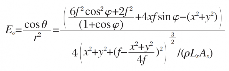
According to the above formula E0, the relationship between the irradiance E0 of the outgoing light at each point of the parabolic mirror and its coordinate point and off-axis angle can be obtained. It can be seen from formula E0 of the irradiance of the outgoing light, that the irradiance of the light emitted by the parabolic mirror is proportional to the radiance of the light source and the luminous area of the light source. The distribution of output irradiance can be calculated by bringing in the specific data. Figure 3 shows the normalized irradiance distribution. The corresponding off-axis parabolic mirror focal length is f=956 mm, and the off-axis angle is φ=10°. It can be seen that the irradiance distribution after the light emitted by the point light source irradiates the parabolic mirror is not completely uniform. As shown in the figure, the maximum irradiance differs from the minimum irradiance by about 3 %, the irradiance maximum is located at the edge of the parabolic mirror. It should be noted that the coordinates in the figure are shifted from the coordinates in FIG. 1 , and the midpoint coordinates (70, 70) in the figure correspond to the center point of the off-axis paraboloid in FIG. 1 .
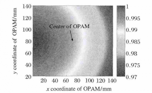
Fig.3 Normalized irradiance distribution on the OAPM surface
When the brightness of the light source is constant, increasing the area of the light source can significantly improve the irradiance of the outgoing light. However, increasing the area of the light source inevitably introduces a new problem, that is, the collimation of the outgoing light becomes worse. As shown in Figure 1, the angle between the light emitted from the edge of the light source and the horizontal direction after being reflected by the paraboloid is α, which is defined as the divergence angle of the collimation system, which is approximately
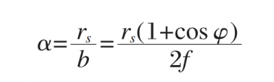
It can be seen from formula above that the larger the focal length of the parabolic mirror, the larger the off-axis angle, the smaller the radius of the light source, the smaller the divergence angle of the outgoing light, and the better the collimation. It should be noted that the collimation quality depends on the requirements of the application, and the divergence angle is not necessarily as small as possible. For example, in the target simulator, the parallel light output by the collimation system needs to have a certain opening angle, so as to simulate the parallel light of different fields of view.
2 Irradiance ray tracing analysis model
The previous analysis gives the expression of the output irradiance distribution when the center of the light source illuminates the parabolic mirror, but when the light source has a certain size, the light off the center point will not be able to use the above theoretical model to determine the output irradiance distribution very well. A good analysis, because the emitted light is no longer a strictly collimated beam at this time, and the irradiance distribution at the exit pupil is closely related to the position of the exit pupil. This paper uses the ray tracing method for further analysis. The most commonly used ray tracing algorithm is the Monte Carlo method (Monte-Carlo).
Generally speaking, when the number of traced rays is small, a large random error will be caused, and the more traced rays, the smaller the random error of the final analysis result, but the required calculation time will increase. Some analysis shows that when the number of ray traces reaches one million, its influence on the system accuracy can be ignored, which can meet the requirements of high-precision simulation. This paper uses ZEMAX software to realize the ray tracing calculation.
3 Ray tracing analysis results and analysis
The parameters of the collimation system to be traced and analyzed are as follows: the diameter of the off-axis parabolic mirror is d=140 mm; the focal length is f=956 mm; the off-axis angle is φ=10°, and the distance from the exit pupil surface to the center of the parabolic mirror is 1000 mm. The optical path diagram corresponding to the above parameters is shown in Figure 4(a).
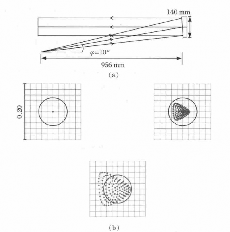
Fig.4 Layout of OAPM in ZEMAX and spot diagram of analysis results
3.1 Collimation performance analysis of off-axis parabolic mirror
First, the collimation of the outgoing light is analyzed, and the “Afocal Image Space” mode of ZEMAX is used for analysis. This mode is specially aimed at the system where the outgoing light is parallel light (ie, afocal system), and can directly analyze the parameters such as the divergence angle of the outgoing light. When the incident light source is an ideal point light source, the collimated outgoing light should be an ideal parallel light. At this time, the divergence angle obtained by ZEMAX analysis is 0°, as shown in Fig. 4(b), which is consistent with the theoretical expectation. When the radius of the light source is 5mm, the corresponding divergence angle can be directly read from the figure as 0.005 2 rad; when the radius is 10 mm, the corresponding divergence angle is 0.010 4 rad. With the help of the spot diagram of ZEMAX, it can be seen that there is a certain dispersion of the outgoing light except the central light source. It should be pointed out that in the “Afocal Image Space” mode, the output unit of the dot plot is radians, not lengths.
Using the above analysis method, for different light source apertures, ZEMAX can be used to calculate the corresponding divergence angle. Figure 5 is a comparison diagram between the ZEMAX calculation results and the calculation results using above formula (formula α) . It can be seen that the results obtained by using above formula (formula α) for theoretical calculation are in complete agreement with the ZEMAX calculation results. The divergence angle has a linear relationship with the radius of the light source. The larger the radius of the light source, the greater the divergence angle.
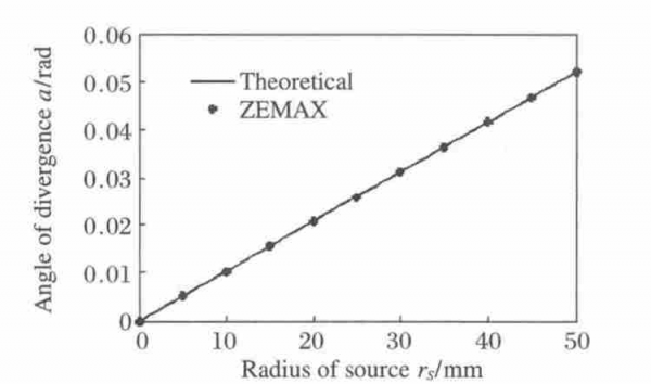
Fig.5 Relationship between angle of divergence and radius of source by ZEMAX and theoretical calculation
3.2 Analysis of irradiance output uniformity of off-axis parabolic mirror
In order to perform ray tracing analysis to obtain the output distribution of irradiance, ZEMAX’s non-sequential model (Non-Sequence Mode) is used. First, import the parabolic mirror type defined above, and then define the characteristics of the light source and the position of the exit pupil surface, and then perform the tracing operation.
The schematic diagram of the ZEMAX ray tracing optical path is shown in Figure 6.
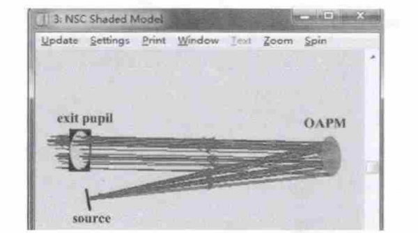
Fig. 6 Schematic of ray tracing for calculation of irradiance distribution on exit pupil plane of OAPM
The light emitted from the light source is reflected by an off-axis parabolic mirror and then propagates to the exit pupil, which is 1000 mm from the center of the paraboloid. In order to obtain reliable results, a total of 10 million rays were traced, of which the light emitted by the light source hit the effective size of the off-axis parabolic mirror about 9.6 million rays. On a common personal computer (CPU: 2.2 GHz, Memory: 4 G), the ray tracing time is about 35 s, the execution efficiency is very high, and the utilization rate of the system light is 96%. Figure 7 shows the irradiance output distribution when the radius of the light source is 5 mm. It can be seen from the figure that the irradiance distribution is generally uniform and circular, and the spot size is basically the same as the diameter of the parabolic mirror. The rectangle size is 150 mm x 150 mm.
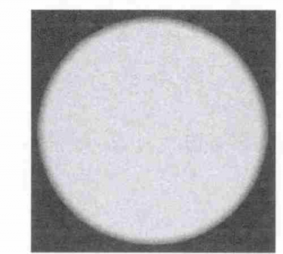
Fig. 7 Calculation result of irradiance distribution on exit pupil plane when radius of source is 5 mm
In order to quantitatively analyze the uniformity of the outgoing irradiance, the distribution of the center line of the cut-out pupil is shown in Figure 8, where the dotted line is the distribution of the light source aperture of 1 cm, and the solid line is the distribution of the light source aperture of 1.5 cm and 2 cm.
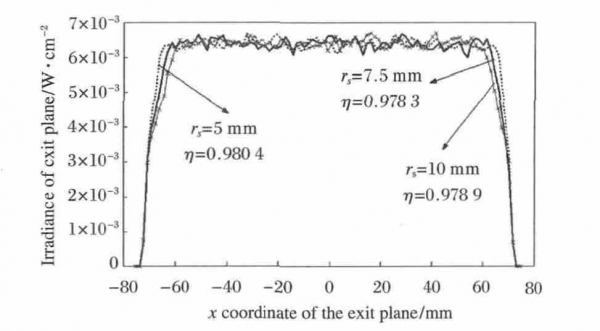
Fig. 8 Irradiance distribution on center line exit pupil plane for different size of source aperture
It can be seen that the distribution law of the three is basically the same, the radiation field energy is mainly concentrated between -70 ~ +70 mm corresponding to the diameter of the parabolic mirror, and the irradiance distribution function is similar to a rectangular function. The closer the shape of the irradiance distribution is to a rectangular function, the faster the irradiance changes in the edge regions. In practical applications such as radiation calibration, since the radiation in the edge region varies greatly and is not uniform, generally only the part with better center uniformity is used. The output irradiance uniformity is defined as:
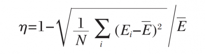
where
Ei is the irradiance of each cell on the exit pupil surface;
N is the total number of cells to be analyzed;
E is the average irradiance of the cells to be analyzed.
According to formula in above, the irradiance uniformity of the three can be calculated to be 0.980 4, 0.978 3 and 0.978 9, respectively, when the central aperture of the analysis spot is 120 cm. It can be seen that under the parameter conditions of this paper, the irradiance uniformity of the output of the collimating optical system based on the off-axis parabolic mirror can be very high, which is basically not affected by the size of the light source.
4 Conclusion
The output characteristics of the parabolic mirror collimation system are analyzed and studied based on two methods of theoretical derivation and simulation calculation. The analysis results can theoretically judge whether the designed collimation system performance meets the actual needs. Using the irradiance transfer model, the irradiance distribution relationship at the exit surface corresponding to the point light source of the system is theoretically given.
The analysis shows that the irradiance of the outgoing light at each point of the parabolic mirror is related to its coordinate point and off-axis angle and other parameters; for the divergence angle, the larger the focal length and off-axis angle of the parabolic mirror, the smaller the radius of the light source, and the greater the divergence angle of the outgoing light. Smaller, the better the collimation.
The irradiance distribution at the exit pupil is analyzed by ray tracing simulation using ZEMAX software. The analysis shows that for the off-axis parabolic mirror diameter d=140mm, focal length f=956mm, off-axis angle φ=10°, the exit pupil surface For a collimation system with a distance of 1 000 mm from the center of the parabolic mirror, when the radius of the light source is 5 mm and 10 mm, the corresponding divergence angles are 0.005 2 rad and 0.010 4 rad, respectively, and the irradiance distribution uniformity at the exit pupil is 98.04% and 97.89%. The analysis shows that the theoretical and simulation results of the divergence angle are in good agreement with each other. The analysis method proposed in this paper is of great significance to improve the collimation and output irradiance uniformity of the off-axis parabolic mirror.