Detailed Introduction of Diffraction Grating
INTRODUCTION
A diffraction grating is an optical component with a periodic structure, which produces periodic changes in the phase, amplitude, or both, of a monochromatic or polychromatic light beam incident upon it. David Rittenhouse, an American astronomer, produced the first diffraction grating around 1785 as a multiple-slit assembly consisting of fine wire. The multiple-slit assembly is a transmission amplitude grating. Diffraction gratings for optical spectroscopy are made by ruling grooves either on a transparent surface to obtain a transmission phase grating or metal surface to obtain a reflection phase grating. Holographic and dielectric gratings are produced using photolithography. Light incident upon a grating is diffracted according to the grating equation
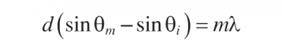 equation 3.1
where:
d is the grating groove spacing
λ is the wavelength of light
θi, is the angle of incidence
θm, is the angle of diffraction for order m that is equal to 0, ±1, ±2, and so on
Equation 3.1 may be written as
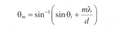 Equation 3.2
To determine the number of diffraction orders recall that -1 ≤ sinθm ≤1. We obtain
 Equation 3.3
Hence
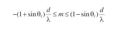 Equation 3.4
The diffraction angle θ0, for zeroth order is equal to the angle of incidence θi, The diffraction angle θ -1 is smaller than θi, for the diffraction order m=-1 and the diffraction angle θ1 is larger than θI, for the diffraction order m=1.This is illustrated for monochromatic light in Figures 3.1 and 3.2 for transmission and reflection gratings, respectively. It is interesting to note that if d<λ, then -(1+sinθi)< m < 1-sinθi. The only values of diffraction order m are equal to 0 and -1.
![]()
FIGURE 3.1 Diffraction angles for 0 and ±l orders for a transmission grating
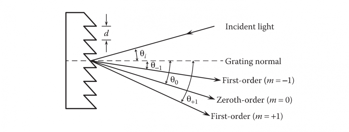
FIGURE 3.2 Diffraction angles for 0 and ±l orders for a reflection grating
The shape of the grooves is usually tailored to obtain most of the light intensity in the first order. Figure 3.3 shows the diffraction angles for wavelengths of 300, 500, and 700 nm for the m=1 order for the light incident normally on a reflection grating with 1200 grooves/mm.
Some spectrometers use the Littrow configuration where θm is equal to -θi,meaning the diffracted light is retro-reflected. The order m is negative for this configuration. The wavelength of the diffracted light is then given by
 Equation 3.5
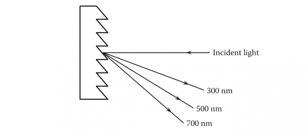
FIGURE 3.3 Diffraction angles for the m=1 order of diffraction
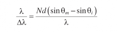
The resolving power λ/△λ of a grating in the Littrow configuration is obtained from Equation 3.5 as

Equation 3.6

Equation 3.7
where sw and fs are the slit width and focal length of the spectrometer, respectively. Equations 3.6 and 3.7 yield a value of 2.5 × 10⁴ for the resolving power of the spectrometer using values of 0.50 m for fs, 10 um for sw, and 0.5 for tanθm. This value of 2.5 × 10⁴ for the resolving power gives a value of 0.02 nm for △λ using a value of 500 nm for λ. Note that sw must be greater than λfs/D, where D is equal to the footprint of the light beam on the grating. Therefore, the resolving power increases linearly with D. The maximum value of the resolving power of a grating is given by
 Equation 3.8
where N is the number of the grating grooves that are illuminated by the incident light beam. Equation 3.8 yields a value of 6 × 10⁴ for the resolving power of the grating using values of 6 × 10⁴ for N, corresponding to 1200 grooves/mm with 50 mm wide beam of light incident upon the grating, and 1 for the diffraction order m. Equation 3.8 may be expressed in the form
Equation 3.9
RULED GRATINGS
Master diffraction gratings are ruled with mechanically controlled ruling engines. Rowland is considered to be the father of modern ruled diffraction grating. In 1882, he ruled gratings of 6-inch widths with more than 100,00 grooves and resolving power in excess of 1.5×10⁵ (Harrison 1949). Rowland and his successors at the Johns Hopkins University designed and implemented a series of ruling engines, each superior to its predecessor. Rowland engines were capable of producing gratings as large as 7.5 inches. Michelson was able to produce gratings as large as 10 inches. One of Michelson’s engines later ended up in Prof. Harrison’s laboratory at Massachusetts Institute of Technology in 1947. Harrison and his team equipped their engine with interferometric position feedback control (Harrison and Stroke 1955). Harrison’s design has become standard practice in modern ruling engines. Contemporary gratings are ruled in thin films of aluminum evaporated on optically flat glass blanks. Because aluminum is fairly soft, it causes less wear on the ruling diamond tool.
Commonly used ruled diffraction gratings are the relatively inexpensive metalized replicas of the master diffraction gratings. Replica gratings are made by pouring a plastic solution over an original grating, evaporating the solvent, and removing the resulting film, which has the grooves of the original grating impressed upon it (Wallace 1905). The removed film is then attached to a substrate.The groove density in the replica is somewhat higher than that in the original grating because of shrink-age of the replica.
Grooves of a diffraction grating are usually shaped to obtain most of the diffracted energy in a given order m for the desired wavelength λ. Such gratings are referred to as blazed reflection gratings. Figure 3.4 shows a blazed reflection grating with triangular groove facets, which are at an angle γ (called the blaze angle) with the grating surface.
For θi = γ ,most of the diffracted energy goes in the direction of the specular reflection from the groove facets, which corresponds to θm =-γ. In this case, the grating equation becomes
 Equation 3.10
For m = 1, the blaze wavelength is given by
 Equation 3.11
For many commercial gratings, the value of sin γ is equal to 0.45, corresponding to γ = 26°45′, so that λB is equal to 0.9d. For example, if there are 1800 grooves/mm, the value of d is 5/9 um. For this value of d, the value of λB is 0.5 μm or 500 nm.
Diffraction efficiency η of a grating depends upon the wavelength of light and its polarization, relative to the grooves of the grating. Figure 3.5 shows typical diffraction efficiency of a 500-nm blazed ruled diffraction grating with 1800 grooves/mm.
Echelle gratings are used for high-resolution spectroscopy. They are coarsely ruled (large d) blazed gratings with a large blaze angle. The resolving power of an echelle grating used in the Littrow mode at the blaze angle is proportional to the tangent of the large blaze angle. Echelle gratings are generally used with a second grating, or prism, to separate the overlapping diffraction orders. Albert Michelson, who referred to them as echelons, discovered echelle gratings in 1898. The resolving
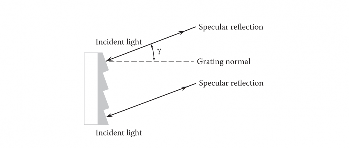
FIGURE 3.4 Blazed grating
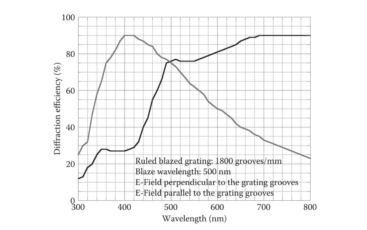
FIGURE 3.5 Efficiency of an 1800-grooves/mm ruled grating
power of an echelle grating relative to that of a conventional blazed grating in the Littrow mode is given by
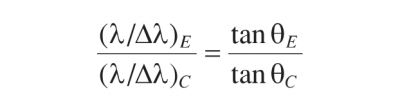 Equation 3.12
where θE and θc are the angles of diffraction for the echelle and conventional gratings, respectively. For values of 75°and 30°for θE and θc, the resolving power of an echelle grating relative to that a conventional grating is equal to 6.5. In other words, the resolving power of the echelle grating with θE of 75° is 6.5 times larger than that of the conventional grating with θc of 30°. That is why echelle gratings are used for high-resolution spectroscopy. Figure 3.6 shows an echelle grating used in the Littrow mode.

FIGURE 3.6 Echelle grating in the Littrow mode
HOLOGRAPHIC GRATINGS
Holographic gratings are produced using interference photolithography, which eliminates the periodic errors found in ruled gratings. Horiba Jobin Yvon produced the first holographic grating in 1967 using two collimated laser beams of the same wavelength that are incident at angle θ upon a photosensitive layer deposited on a highly-polished substrate, as shown in Figure 3.7 (Lerner et al. 1980). A team of Massachusetts Institute of Technology (MIT) students, scientists, and engineers have developed the world’s fastest and most precise tool, the Nanoruler, for producing large holographic gratings (Chen 2004). The Nanoruler can fabricate holographic gratings 10-1000 times faster and more precisely than previous methods.
Holographic gratings have two groove profiles: sinusoidal and blazed. Most of the holographic gratings have sinusoidal groove profiles, which are symmetrical and therefore have no blaze direction. The efficiency of a holographic grating with sinusoidal groove profile is usually less than that of a ruled grating. However, a holographic grating with a sinusoidal groove profile has nearly the same efficiency as a blazed ruled grating when the groove spacing is comparable to the wavelength of light. A blazed holographic grating has a saw-tooth groove profile, which has higher efficiency than that of a holographic grating with sinusoidal groove profile. Replicas of holographic master gratings are produced using a process identical to that used for ruled gratings. Figure 3.7 shows a schematic for the recording of a holographic grating.
The spatial period of the grating is d= λ/(2sinθ). Hence for θ> sin-1 (1/2), the grating period becomes less than λ. In the extreme case,grazing angle d= λ/2.
Figure 3.8 shows the efficiency of a holographic grating with 1200 grooves/mm. Note that the efficiency of the holographic grating shown in Figure 3.8 is quite comparable to that of the ruled grating shown in Figure 3.5.
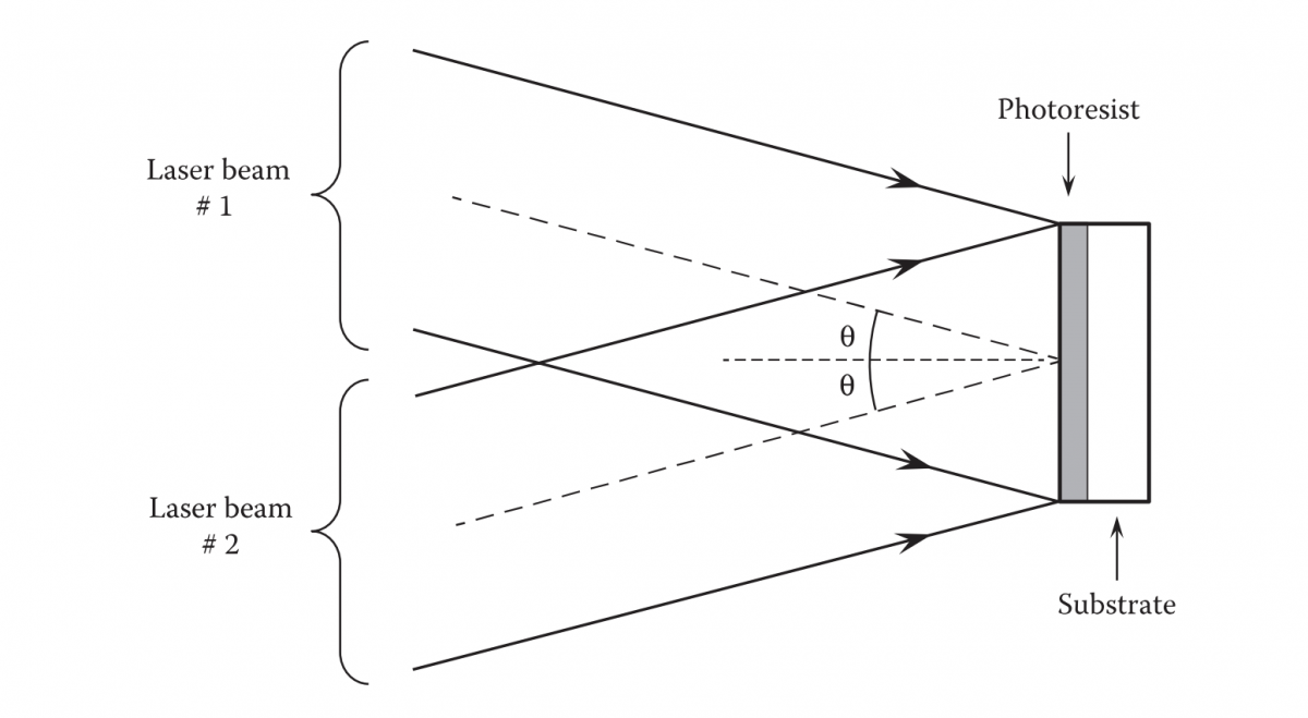
FIGURE 3.7 Recording of a holographic grating
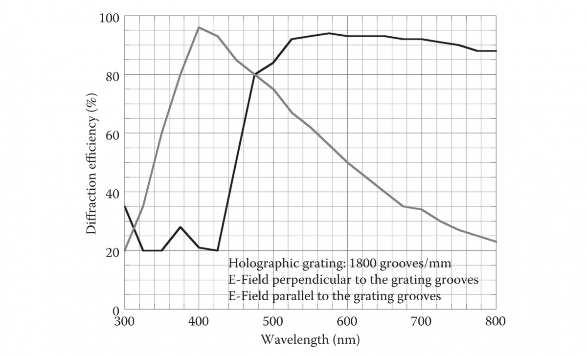
FIGURE 3.8 Efficiency of an 1800-grooves/mm holographic grating
MULTILAYER DIELECTRIC GRATINGS
Multilayer dielectric gratings provide high diffraction efficiency (>96%) for TE-polarized light in the m=-1 order in reflection and high damage threshold above that achievable with metallic gratings. The diffraction efficiency is low (<50%) for TM-polarized light (Perry et al.1995). Figure 3.9 shows the basic multilayer dielectric grating structure, which consists of alternate layers of materials of high (dark bands) and low (white bands) refractive indexes. The groove height and the top layer thickness are denoted by h and t, respectively. High diffraction efficiency occurs when the optical path of the grooves is near one quarter of a wave and the optical thickness of the top layer is near three quarters of a wave. The peak diffraction
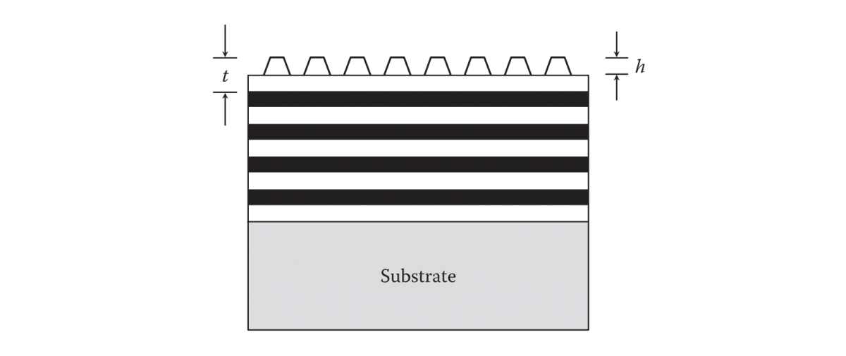
FIGURE 3.9 Structure of a multilayer dielectric grating
efficiency (order m=1) has been predicted to be near 98% for TE-polarized light and less than 50% for TM-polarized light at 1053 nm of a grating consisting of alternate layers of ZnS (n=2.35) and ThF4(n=1.52). Multilayer dielectric gratings could be designed for any wavelength using appropriate materials.