Requirement for images and Resolutions
Taking a photograph or taking an image in general, of course, only makes sense, if we make use of it. If, for the moment, we disregard special scientific or technical applications, usually the goal is to provide good images and to view them. To do so, it is required that the recorded image is made available by a particular output device such as a printer, a screen, or a beamer and then we look upon it. Of course, this is an image process again, with the original image, i.e., the photograph, now acting as the object.
However, in contrast to before, where the real object consists of an infinite number of object points, now the observed photograph may be described by a finite number of points (better: spots), which now act as new “object points” for further observation (again an imaging process; note again: this is a model; in reality there is an infinite number of overlapping image point distributions).
This “second imaging process” (second with respect to the original scene captured by the camera) is performed by the most important (optical) imaging device for humans, namely the human eye. In contrast to us, bats and dolphins, for instance, use acoustic signals for image formation. Hence, for us it makes sense to relate images and their content to the physical properties of the eye. Within this introduction chapter, we will restrict ourselves to the previously mentioned properties resolution, ascertainable information and SBN. To get an idea of what we require from an image, we have to have knowledge of the performance of the human eye. Here, in particular, we do concentrate on two properties: its optical resolution and the angle of view ψ. Relation to other properties, such as “depth resolution”, will be made in later chapters.
1. Resolution and angle of view of the human eye
Unlike image formation by conventional technical systems, our human visual perception is a very complex process due to the physiological structure of the eye in combination with its behavior in viewing objects.
A standard camera produces an image of a scene where in the ideal case all parts of the object space are imaged simultaneously to the image sensor. Ideally the sensor is homogenous with respect to its resolution and sensitivity. The human eye, on the other hand, has great similarity to a camera, but the resolution on the photosensitive retina is not homogeneous, being the highest in a region called the macula, approximately 3mm in diameter (Figure 1).
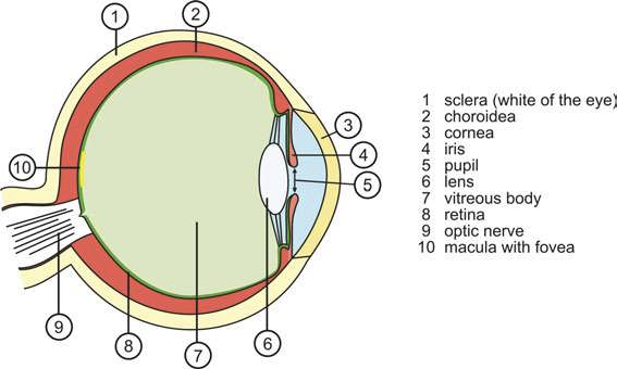
Fig. 1 Schematic structure of the human eye (author Talos4)
Thus with decreasing brightness the color impression and resolution degrades as the cones are only weakly sensitive at dim light, and night vision can be characterized by almost black-white imaging at lower resolution. Additionally the spectral range for highest sensitivity of the eye shifts from the green for day vision to the blue range for night vision.
The highest visual acuity of the eye is found in the center of the macula in a rod-free region of around 0.2mm diameter, called fovea. As a consequence, in cases where it is required to see sharply over a larger region, the eye must permanently scan the area of interest and then, in conjunction with the brain, the visual impression is constructed.
As a field of view of the human eye, we understand the range of visual perception. If the eye is at rest, the part of the image that covers the macula is the center of the image and is perceived with the highest resolution and sensitivity. The visual acuity decreases with increasing distance from the image center. At the periphery only a blurred or shadowy image impression is possible. Points in the field of view that are perceived by the same sensitivity are in general located on closed curves termed isopters.
Figure 2a illustrates schematically some isopters (yellow lines) as a function of the angle in the field of view for the right human eye, measured by kinetic isopter perimetry. The white area represents the blind spot in the eye where the optic nerve passes through the retina and where no perception is possible. The isopters are nearly concentric and asymmetric with a wider lateral extension due to shadowing by the nose.
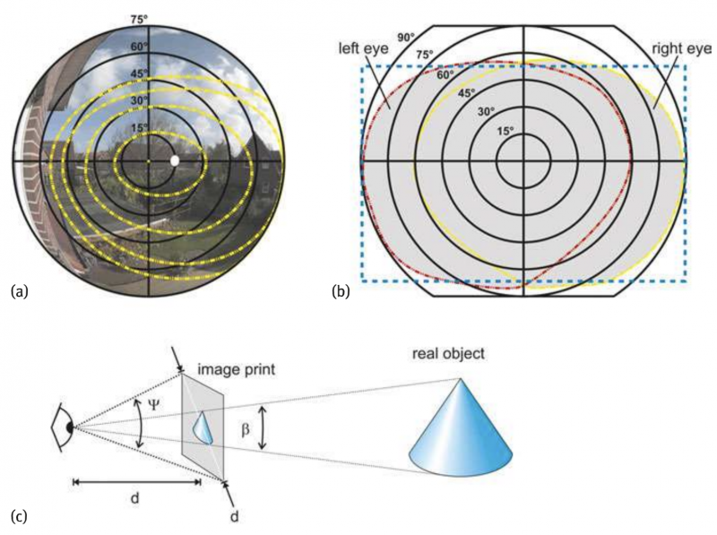
Fig. 2 Field of view for the human eye. (a)schematic illustration of isopters for the human right eye (yellow curves), indicating lines of constant:sensitivity to light variation, measured by kinetic isopter perimetry. The white dot indicates the position of blind spot. The background image is taken by a fisheye lens of 150° of total angular field of view. (b)schematic total binocular field of view (gray area); the dotted frame is a rectangle with a 3:2 width/height aspect ratio; (c)the total angular field of view for an image viewed at the distance d of the image diagonal yields ψ≈53°.
Only four isopters are shown for illustration purposes, but there are also curves beyond 90° from the optical axis. The closer the isopters are to the center the higher the sensitivity of the eye. The peripheral isopter in Figure 2 is measured using full intensity of the test light, the subsequent inner isopters are taken for 1/3, 1/10 respectively 1/30 of the full intensity.
Seeing with two eyes for stereoscopic vision, the brain constructs a total optical impression, which is larger than that of an individual eye. As a result the total binocular field of view extends to more than 180° in horizontal direction whereas in the vertical direction it is of more than about 120° with wider extension to the lower part. The binocular field of view is schematically depicted in Figure 2b. Only the central part, which is enclosed by both isopters for the right and left eye, is seen simultaneously by both eyes for stereoscopic vision.
For comparison, a rectangular frame of an aspect ratio 3:2 is shown in the figure. It can be seen that image sensors or films of a similar shape and aspect ratio are well appropriate for representing visual human perception.
Moreover, Figure 2a also shows the image taken by a fisheye lens with a total angular field of view of about 150°. Unlike for human vision, we have here nearly the same resolution all over the image field. From that consideration it becomes difficult to define an angle of view for the human vision in the same way as it is normally done for technical optical systems.
However, in order to fix a reason-able value for the angle of view of the human eye, a different approach taking into consideration the psychology of seeing as well as the habits for observing images is necessary.
Let us assume a distinct visual range of 25 cm for reading a text or clearly ob-serving an image. The image size must be adequately large to feel comfortable when looking at it. Empirical values show that this is the case if the image diagonal is approximately identical to that distance of 25 cm or slightly smaller. Then the eyes of the observer can comfortably scan the total image at high visual resolution. If the image diagonal d is equal to the observing distance or slightly less, the total angle ψ is (Figure 2c):

If a photo, which is observed under this condition, has been taken using a lens with the same angle of view, a very natural perspective and a plastic, nearly three-dimensional impression is achieved. The angle β under which the imaged object on the image print is perceived is identical to the angle under which the real object is perceived by the observer when taking a photograph of it (Figure 2c). These considerations as well as some technical aspects to optimize lenses for a 35 mm-film format with a43mm image diagonal may have inspired the lens designers of Leica in the years around 1920 to fix the focal length of the normal lens for that film format to 50mm. The angle of view for this lens is nearly 47°. Thus the angular field of view ψeye for the human eye can be assumed to be between 47° and 53°. We will use in this book ψeye = 47° as a reference value for the human eye.
As described above, the resolution of the human eye is not homogeneous across the retina. The acuity of vision depends on different parameters as for instance, illumination, object distance and structure, as well as the symmetry of the observed object. The evaluation of the resolution is not as straightforward as for optical systems. Thus a broad range of values for the angular resolution of the human eye can be found in the literature.
Two objects, as for instance, points or lines, can be discriminated as being separate at an observation distance of l = 25 cm if their separation distance δ is between 75 μm up to 300μm for comfortable vision(Figure 3a).This situation is for small dots contacting each other. The corresponding visual angular resolution △φ is given by∶

Using the above values for l, respectively δ yields for △φ values between 1′ and 4’of arc, respectively 0.3 to 1.2 mrad. The minimum value of 0.3 mrad means that two human hairs close to each other can still be discriminated at a distance of 25 cm.
This is compatible with the perception of smallest apertures in a Landolt-ring which is used in ophthalmology to determine the human visual acuity (Figure 3b). If very narrow structures or deviations from symmetry should be detected, even values below 1′ of arc can be found. This is the case for instance if the nonius of a vernier caliper is observed. Here values of 5″ of arc to 10″ of arc for △φ may be found. Taking all these different aspects into consideration, it is very difficult to specify the resolution of the eye as is done for technical optical systems. We think, however, that △φeye = 0.6 mrad, respectively 2′ of arc, is justified as a mean value for the angular resolution of the human eye in many cases.
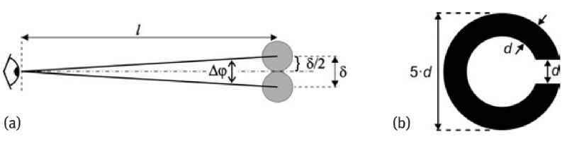
Fig. 3 Angular resolution of the human eye. (a) As determined by discrimination of isolated objects; (b) as determined by the perception of a Landolt-ring. The stroke width d is identical to the gap width; the diameter is 5.d.
This value will be used as our reference if a comparison with optical systems is needed in this book. In some cases a higher resolution is required, for instance in order to ensure that aberrations of the optical system, like camera lenses, should not be perceived by the human eye. Then 1′ of arc or is more appropriate. This is a challenging value, which lens manufacturers use for the design of high quality lenses. If for instance we view an image print of 12cm×18cm, having a diagonal of 21.6 cm, from a distance of 25cm then the angular resolution of 1′ of arc corresponds to a distance of 73 μm on the print.
This is 1/3000 of the image diagonal and is the limit value for details that can be perceived on the image for the described viewing condition. If the print is a 5x magnification of an original image taken by a 24 mm×36mm full format sensor with a diagonal of 43mm, 1/3000 of its diagonal corresponds to 15 μm. Structure details on the sensor with dimensions below 15μm can no longer be detected by the human eye even on 5× magnified prints observed from the distance of its diagonal. This is decisive for the allowable circle of confusion that can be tolerated by optical systems.
Based on those definitions one may approximate the maximum number of “image points” that could be distinguished within the width of an image (i.e., in one dimension) and thus we get for a consideration in one dimension:

For a two-dimensional space, neglecting differences in angle of view in horizontal and in vertical direction, SBN may be roughly estimated by the square of the value given by equation in above.
According to the values given above by ψeye = 47° and △Øeye = 2′ of arc for the human eye we may estimate NSB,eye ≈14000 or roughly 1500. With the more challenging resolution of △Øeye = 1′ of arc we may obtain instead NSB,eye≈ 2800 or roughly 3000 but not, for instance, 10 000 and thus at least get a feeling of the image contents that may be captured by a human eye “at once”. This means that from a typical photograph with an aspect ratio of 3:2 (or 4:3), which fully covers the human angle of view in one direction in the best case, we may estimate that we could resolve approximately 3000 “image points” in this direction and 2:3 (or 3:4) times less in the other one.” Thus in total the maximum possible space bandwidth number for the eye is NSB,eye≈ 5·106. This is the number of perceivable “image points” in two dimensions (note: not pixels).
2. Remarks to reasonable number of “image points” and SBN in photography
From this estimation it is clear that usually it makes no sense to increase the number of “image points” within an image, namely the SBN, much beyond the value given by NSB,eye. Only if we are interested in large posters where high resolution at close observation distance may also be required, then images with NSB 》NSB,eye have to be provided. However, then we see only a fraction of the whole scene, albeit at high resolution. On the other hand, if the number of “points” is significantly fewer than in NSB,eye, the image contains less information than what is possible at maximum and thus image quality is worse.
Thus an image that has the discussed optimum SBN, which is NSB,eye for the human eye, provides less information, i.e., a lower SBN, when observed from a closer distance. The reason is that in this case we see only a fraction of all of the “image points”, which can now be perceived as larger blurs, but we cannot see more details. The limitation is given by the original”image point” size of the observed image.
On the other hand, when the original image is observed from farther away we do have a similar situation. Due to limited resolution of the eye, we cannot resolve the original “image points”. The eye only recognizes fewer “image points” within the image, which again, is equivalent to a reduced SBN of the captured image.
3. Magnified images
Depending on how magnification of an image is performed, one may discriminate different situations. To do so, let us take an image with a given fixed number of “image points”, i.e., a given SBN (image 0) and consider two situations.
I) Let us regard a simple magnification of such a full image (“image I”). Because both PW and δx, and PH and δy, respectively, are enlarged by the same factor, SBN does not change and thus the information content for the magnified image is the same as before. NSB, namely the number of “image points”, is independent of its absolute size. This means also that we cannot recognize more details in the magnified image and thus magnification does not lead to a better resolution; only the size of the region and that of the “image points” is increased. This situation is given when printouts of different sizes ale made from the same picture taken by a camera.
II) Now let us regard a simple magnification of a given fraction of the full image (“image II”). In particular, we compare a selected region of interest (ROI), such as the one marked in Figure 4a but now enlarged to the same size as Figure 4a. Of course, SBN within the marked region is the same as in the expanded full image Figure 4b, but it is much smaller than the SBN of the full image Figure 4a.
This is the so-called software zoom and leads to a loss of information content. This may be even more apparent when the ROI marked in Figure 4b is compared to Figure 4c, which was taken by a telephoto lens. Ideally, SBN in Figure 4a and Figure 4c is the same, but the quality of the image Figure 4b is worse. Usually the software zoom may be applied when taking photographs with a digital camera. However, unless one is interested in saving recording space, it is recommended to avoid it, because this is always coupled with loss of information. If the image should be magnified anyway, this can always be done later in a post-processing step using a computer. Then there is even the advantage of selecting different ROI more properly.
III) For comparison to before, let us regard a true zoom or an image obtained from a fixed telephoto lens (“image III”). In this case, we do not enlarge the image discussed before, but instead we take another one by applying different optics. Such a telephoto lens has a reduced angle of view ψ, but also a better angular resolution △φ when compared to before. At best, this tele-photo lens has the same SBN as that of the optics used to capture the image 0, and thus no loss of information occurs. Figure 4c illustrates this situation. This example also clearly shows the advantage of a photo camera with exchangeable or zoom lenses, respectively, when compared, e.g., to almost all mobile phone cameras. The first one does allow for high quality hardware zooms, whereas the latter ones do not. As usually the in-built lenses are wide-angle lenses with fixed focal length, any zoom is automatically a software zoom with the discussed significant disadvantages.