Diode-Pumped Nd:YAG Green Laser with Q-Switch and Mode Locking
Gaining of a high peak power in the visible light range from a solid state laser with continuous diode pumping is a challenging task in several applications (high-precision material processing, nonlinear optics and Raman-spectroscopy, medicine, etc.). The technique of modulating the Q-factor of laser cavity (Q-switch) enables growth of the peak power approximately as τsp / τph (here τsp is the upper laser level lifetime and τph is the photon lifetime in the cavity).
When we take a typical Nd:YAG laser, this gain in peak power is about 103- 104 times. The further growth of the peak power is possible through methods of mode locking of the laser (ML).
However, realization of mode-locking together with Q-switch (unlike the case of continuous operation mode) is a technically challenging task: we face a high amplification, almost uncontrollable nonlinear effects, damage of optical elements in the laser, etc.
In prior art, the steady mode of generation for Q-switch coupled with mode locking (so called QML) is accomplished with using of two acousto-optic modulators (AOM) in a cavity; one modulator operates in the traveling acoustic wave, and the other modulator has the standing wave (see, e.g., Kuizenga, 1981).
Actually, the QML mode is possible when we introduce absorbing elements within the cavity (Herrmann & Wilhelmi, 1987; He et al., 1996; Chen et al., 2001; Agnesi et al., 2001; Pan et al., 2007), but in this case the higher pumping level means a higher pulse repetition rate.
Therefore the practical levels of peak power are very moderate. In this chapter we inform about a new technique for obtaining a steady QLM lasing mode in a diode-pumped green Nd:YAG laser; this type of operation is possible with only one travelling-wave AOM. As for the further shortening of lasing pulse duration (Δτ), it is achieved through formation of a Kerr lens in a doubling-frequency crystal. Since the process of make-up a Kerr lens is very rapid, this trick gives us Δτ as small as the theoretical limit ≈ 1/Δν (here Δν is the spectral bandwidth of generation).
The general scheme of experiment and key parameters of Nd:YAG laser
Now the class of solid-state lasers demonstrate a rebirth due to replacement of pumping with arc lamps by diode-laser pumping; this ensures a higher efficiency of the device (higher than 10%) and a longer service life (more than 10,000 hrs).
Typically, diode laser (DL) can be used in different schemes of pumping – longitudinal or transversal. Solid-state lasers with longitudinal pumping are more efficient and the emission beam has better quality (М2 ≈ 1) (Tidwell et al.,1992; Tsunekane et al., 1998).
However, it is very difficult to gain a high output power at this geometry of pumping. When the required output power is above 100 W, the good choice is lasers with transverse pumping of the active element (e.g., in Ostermeyer et al., 2002; Fujikawa et al., 2001; Lee et al., 2002). But the efficiency of this scheme is lower and lasing with М2 ≈ 1 usually faces serious difficulties.
In this paragraph we describe the experimental scheme of a Nd:YAG laser with transverse pumping by DL arrays and with time-averaged output power of 15 W (in ТЕМ00-mode).
When the effective doubling of laser emission frequency is achieved, this scheme enables lasing with the output power of 12 W (here the wavelength is λ = 532 nm). The laser scheme with a Z-shaped and 4-mirrored cavity (Donin et al., 2004) is depicted in Fig.1. The reflection coefficient (r) for mirrors М1-М4 at the wavelength 1064 nm was better than 99.5%. Mirror М4 was a dichroic mirror with r > 99.5 % (at λ=532 nm); at the latter wavelength the transparency coefficient (T) for mirror М3 was 92 %.
To gain the light generation at the second harmonics between spherical mirrors M3 and M4 (they have curvature radii R =200 and 150 mm, correspondingly), a nonlinear crystal (ВВО, КТР or LBO) was placed into the zone of cavity waist . The beam diameter in this zone was about 100 -150 µm. To gain a maximum power of emission at the wavelength λ=1064 nm, the mirror М1 was replaced with a mirror possessing an optimal transmission coefficient (but there was no need in the nonlinear crystal within the resonator).
The active element was a Nd3+ :YAG crystal (mass concentration for Nd was 1 %) with the diameter of 2 mm and the length of 63 mm; this element was illuminated from three sides with bars of LD arrays emitting at the wavelength λ р =808 nm (Fig. 1b). The laser’s active element together with DLs is cooled by distilled water flow. This cooling is accomplished by a circulation-type close-loop cooler; this device ensures temperature stability within 0.1 0С.
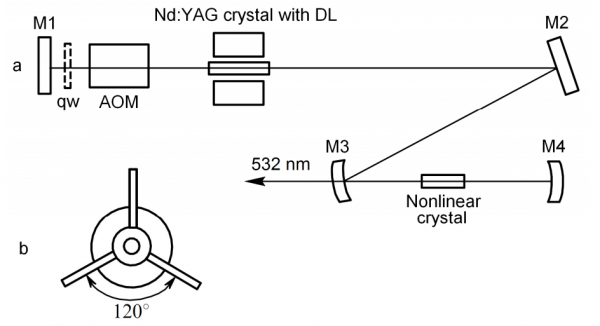
Fig. 1. Scheme (a) and pump geometry (b) of an Nd:YAG laser: M1 – M4 – resonator mirrors, qw –quarzrotator.
The operation temperature of laser was close to 28 0С and it can be regulated in a wide range. The dependency of laser output power on the coolant water temperature is plotted in Fig.2. The Q-factor of laser was modulated with the MZ-305 type AOM with the travelling acoustic wave. The AOM with the driving frequency of 50 MHz was manufactured from crystalline quartz and equipped with water cooling facility. The quarzrotator 5 could be used for compensation of induced birefringence.
The laser resonator was calculated with the matrix method with account for a heat lens in the
active element and dispersion of the air gap between the nonlinear crystal and mirror 4. We have also estimated the diffraction losses of ТЕМоо-mode (≈ 10%) and higher-order modes, e.g., for TЕM01 mode (≈ 50%). All these losses ensured lasing in the regime close to ТЕМоо-mode.
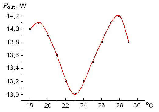
Fig. 2. Output laser power vs. temperature.
When the dimensions of the active element were chosen in the view of most effective usage of this element, we took into consideration the following things. During of active element pumping, the birefringence effect takes place: this causes depolarization of beam passing the crystal and makes the losses higher. The depolarization-caused losses are proportional to ω4, and the output power has the law ω2 ( here ω is the radius of ТЕМ00-mode in active element).
This means that we can find the optimal value for the resonator’s fundemental mode. The estimate for optimal ω for our conditions was about ≈ 1 mm; this coincides with results from (Matthew et al., 1996). Therefore the optimal diameter of rod should be take ≈ 2 mm.
The dependencies of output power (Pout) of the laser at λ=1064 nm (at the AOM switching frequency or the pulse repetition rate F = 20 kHz) on the current (I) through DL, as well as function оf emitted light power (Plight) and consumed electric power (Рelectr) of DLs are plotted in Fig.3. The saturation of Pout along with current growth is caused by the resonator mismatch due to thermo-optic effects.
The thermal lens in active element has the focal distance (at saturation current) close to 25 cm. The efficiency coefficient on the total electric power was 5%, and the light efficiency was 12.5 % (the differential coefficients of efficiency were 10% and 21%, correspondingly). These curves were obtained for a configuration with an exit mirror M1 (see Fig.1) which has the optimal transmission coefficient Т = 20 %. Under described conditions, generation took place in the ТЕМоо-mode.
Fig.4 shows the plotting of the output power and the lasing pulse duration Δτ vs. the pulse repetition rate (F). The pulse length was measured with an avalanche photodiode type LFD-2 with the time resolution better than 1 ns.
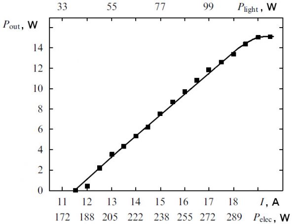
Fig. 3. Dependence of the 1064 nm output power on the current, light output power and the consumed electric power of the DL.
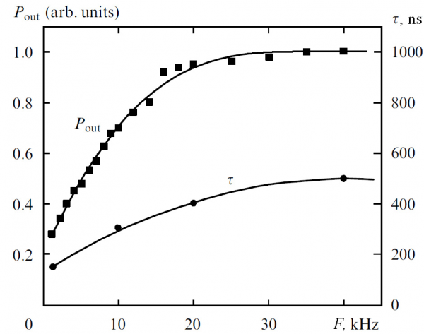
Fig. 4. Dependence of the output power at 1064 nm and the laser pulse duration on the pulse repetition rate.
Frequency doubling for laser emission
Let us focus on the problem of frequency doubling (second harmonic generation) for laser emission. It is known (Smith, 1970) that while intra-cavity frequency doubling the losses brought by a nonlinear crystal must be balanced to the losses brought by an optimal mirror for a laser without nonlinear crystal. This condition enables a maximum output power at the doubled frequency.
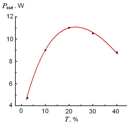
Fig. 5. Laser output power (λ=1064 nm) vs. transmission of output mirror T.
Fig.5 presents an experimental plotting of laser output power as a function of transmission coefficient for the output Mirror (DL current I = 17A).
In choosing the type of nonlinear crystals for the second harmonic generation and picking up optimal parameters (including the crystal length dcr ), we made computer simulations for the double-frequency output power. These simulations started from a system of truncated equations for the real parts of electric field amplitudes; this system of equations was derived from the wave equation by the method of slowly varying amplitude in low-absorption and low-nonlinearity medium within the plain wave approximation.
These equations were solved by using software specially developed for determining the all required parameters of nonlinear crystals (even in the case of deviation from precise phase matching). We applied a simple differential scheme for a particular case of second harmonics generation when effects with normalized phase (Δkz + π/2) accumulates most rapidly. At the initial conditions z=0, a2(0)=0 we solved numerically this equation system (Dmitriev & Tarasov, 1982)
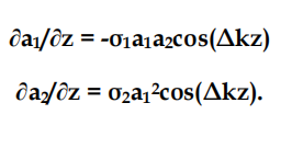
For the case of precise phase matching (wave detuning Δk*=*2k1-k2=0) this equation system has an exact analytical solution:
![]()
Here σ1=4π2deff/λ1n1, σ2=2π2deff/λ2n2 are the nonlinear coupling coefficients, deff is the effective nonlinearity, λi is the wavelength, ni is the refraction index, ki is the wave vector, аi is the electric field amplitude, а10 is the initial amplitude of the electric field for the fundemental emission, z is the running coordinate.
In these calculations we took the formulae and input data for calculating the effective nonlinearity deff and Sellmeyer’s equations for determining the refraction index ni as in (Linet al., 1990; Gurzadyan et al., 1991). The phase-matching angles for the wavelengths of fundemental radiation (1.07-0.75 µm) were calculated by well-known formulae (see Dmitriev & Tarasov, 1982).
These calculations were performed for nonlinear crystals LBO, КТР, ВВО. Fig. 6 presents calculated the second-harmonic power density S2 as a function of the crystal length. We took the power density of fundamental input radiation S1(0) equal to 150 MW/cm2, which corresponds to the Q-switch frequency F = 10-15 kHz. The power density was defined as Si = c ni аi2/8π, here c is the velocity of light in vacuum. The approximate lengths of crystals which are optimal for generating output power at the second harmonics are the following: ≈ 10 mm (LBO, phase-matched type I), ≈ 2 mm (КТР, phase-matched type II), and ≈ 5 mm (ВВО, phase-matched type I ).
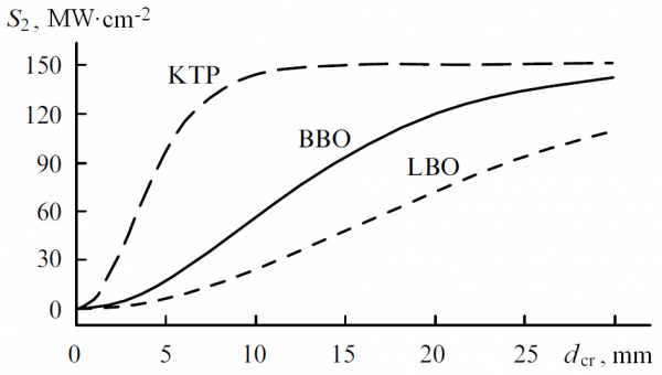
Fig. 6. Calculated dependences of the second-harmonic power densities S2 on the crystal length.
The walk-off angle was calculated by formula
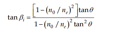
where θ is the phase-matching angle, no and ne – ordinary and extraordinary refractive index. The same software was used for estimating of the angular and spectral phasematching width.
In our experiment on study of the second harmonics generation, we used the ВВО crystals (phase-matched type I: θ=22.80, φ=900; dcr =5 mm), КTP (phase-matched type II: θ=900, φ=23.50; dcr =5 mm), and LBO crystal (phase-matched type I: θ=900, φ=11.60, dcr =12 mm).
All the tested crystals had two-hump antireflection coatings at the operating wavelength with r < 0.5%. This allowed us to obtain the maximal power of generation: ВВО – 5 W (F=15 kHz), КТР – 12 W (F >20 kHz), and LBO – 8.3 W (F = 10 kHz). We should note that for the BBO crystal the maximal power was restricted by coating destruction.
A typical dependence of second-harmonic output power on the DL current for a LBO crystal is shown in Fig.7. One can see that at the initial interval, this dependency has the second power law, but later it goes slower due to resonator mismatch caused by thermo-optic effects. The curve of output power vs. the pulse repetition rate frequency for an LBO crystal had a maximum at the F = 10 kHz.
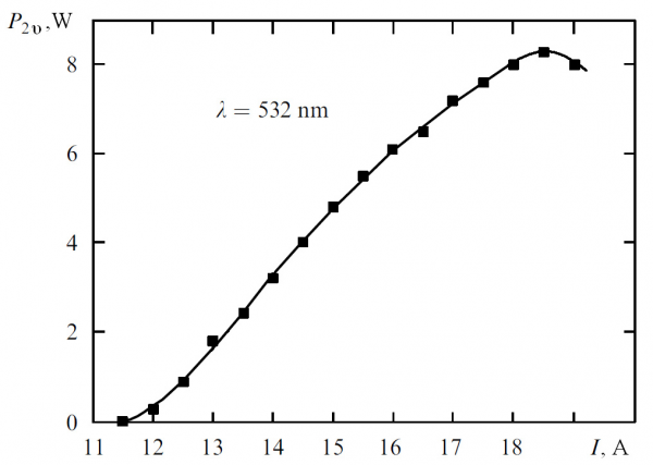
Fig. 7. Dependence of the second-harmonic output power P2ν on the DL current I for an LBO crystal at F = 10 kHz.
For a KTP crystal, the generated power is growing steadily up to F=20 kHz, and becomes constant in the interval from 20 to 40 kHz. For a KTP crystal, the coefficient of conversion into second harmonic was 80 %. For LBO the maximal power of second harmonic was obtained at driving frequency of 10 kHz, and this corresponds to 10.5 W generation at wavelength λ=1064 nm (Fig.7). Therefore, the coefficient of conversion into second harmonic for this type of crystal was 79%.
Fig.8 presents the dependency of pulse energy and peak power at the wavelength 532 nm as a function of Q-switch frequency (the case of LBO crystal and a cavity on Fig. 9).
Our results demonstrated the efficient conversion of the fundamental frequency into the second harmonic for the case of Q-switched pulse energy ≈ 1 mJ; this gives hope for developing an effective laser with output at wavelength λ = 532 nm and with the average output power for ТЕМ00-mode as high as 100 W and even higher.
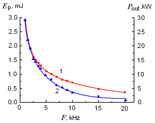
Fig. 8. Dependence of pulse energy Ep (1) and power Pout (2) at λ = 532 nm on the pulse repetition rate F.
Q-switch and mode locking achieved with a travelling-wave AOM
Here we develop a new method (Donin et al., 2011) of QLM lasing; the design includes a end-spherical mirror (SM) in the cavity and one travelling-wave AOM (abbreviation – SMAOM). The operation principle for SMAOM configuration and laser scheme is illustrated in Fig. 9. The Nd:YAG green laser was assembled by the key diagram shown in Fig.1.
The mirror curvature radii were 200, -900, 200 and 150 mm accordingly for the mirrors M1, M2, M3 and M4. The cavity optic length was L =1.5 m. The АОМ was placed at the Bragg angle (θB) to the optic axis of cavity near the terminal spherical mirror М1.
The AOM’s center is distanced from the mirror’s reflecting surface by distance R1, which is the mirror curvature radius. When the driving frequency is f = 50 MHz, which equals a half of laser’s intermode interval c/2L =2f , a travelling acoustic wave is created in the quartz block of AOM (it is shown by small bold-symbol arrow in Fig. 9); this travelling wave is a source for Bragg’s diffraction for laser emission. Since the light beam (with frequency ν0) passes through the AOM from right to left, two beams enter the mirror (1 and 2).
Beam 1 goes along the cavity axis and being reflected from the mirror backward without any change in initial frequency ν0. The beam 2 feels the Bragg diffraction and travels to the same mirror with frequency (ν0+f). The reflects from the spherical surface of the mirror and returns to the AOM, where it is split into a beam with the unchanged frequency (ν0+ f), exiting the cavity in the backward direction at the angle 2θB, and another beam after repeated diffraction (on the AOM’s quartz block). The latter kind of beam has a frequency (ν0 + 2f) and travels backward along the cavity axis. This beam produces the effect of mode locking.
The beam with frequency (ν0 + f) exiting the cavity at angle 2θB provides modulating of losses in the cavity; so the laser operates in the mode of Q-switch with the pulse repetition rate which is given by the AOM switching frequency (F~1÷100 kHz).
The good feature of this scheme is that when the driving frequency is off, the acoustic wave inside then AOM dies during a time t = db/Vsnd = 0.2cm/5·105 cm/s ≈ 0.4 µs (here db is the laser beam diameter in the quartz block, Vsnd is the sound velocity in the material). The duration of the lasing pulse in the Q-switch mode was ≈ 100 ns, i.e., during time t due to the beam of repeated diffraction with frequency (ν0+ 2f) mode locking is achieved in the generation pulse.
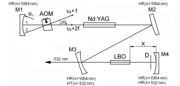
Fig. 9. Laser diagram and operation principle for SMAOM.
М1-М4 – cavity mirrors, АОМ – acoustic-optic modulator, Nd: YAG – active element, LBO – nonlinear crystal, D – diaphragm
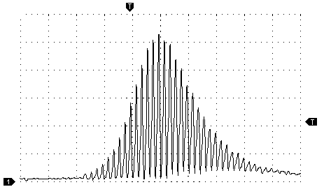
Fig. 10. Oscillogram of generated pulse at the wavelength λ = 1064 nm produced in QML mode.
The division value for abscissa axis is 50 ns.
On the first stage, we performed measurements without nonlinear crystal and diaphragm (this means no frequency doubling and no Kerr lens formation). In this case we replaced the mirror М1 with another one with similar curvature radius, but possessing the transparency of Т = 11% at λ = 1064 nm.
The oscillogram of a Q-switch pulse with mode locking is depicted in Fig.10. The average power of laser was 2 W (at the Q-switch frequency equal to 2 kHz). The registration system resolution time (photodiode and oscillograph) ≈ 2 ns did not allow us to determine the actual duration of pulses inside a “train”, so this task had required assembling an optical correlator for pulse registration on the second harmonic in the KTP crystal (collinear scheme). This optical correlator gave the pulse duration for mode locking generation about 40 ps (see Fig. 14 а), i.e., a single peak power was ≈ 2 MW.
The Kerr lens based on nonlinear crystal
The further gain in reducing a single pulse duration and growth of its peak power has been achieved using a Kerr lens and a diaphragm (laser generation at the line λ = 532 nm as shown in Fig. 9). Kerr lens is formed in a nonlinear crystal for 2nd harmonic generation (LBO, phase-matched type I, the length of dcr = 20 mm). For the first time, the phenomena of mode locking with a Kerr lens (or self-locking of mode) has been studied in (Spence et al., 1991). The foundation of this method is a radiation self-focusing in a media; this opens the way to creating an affect similar to absorbing elements in a laser cavity.
Self-focusing develops due to dependency of material refraction index on radiation intensity: n = n0 + n2I.
This effect creates a lens with focus depending on light intensity. This type of nonlinear lens matched with a diaphragm works as a kind of saturable absorber. Another design is too possible: the same lens without a diaphragm, and the cavity elements work as a diaphragm.
In the case when self-focusing is driven by electron polarization under impact of the field of light wave, this would create an almost zero-inertia “saturable absorber” – the response time is ~10-15s (see, e.g., Shapiro, 1977). The calculating of cavity’s parameters was done with the matrix method. The following matrix was used for describing the beam passing through the Kerr element (Magni et al., 1993):
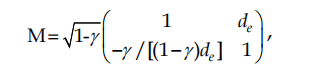
where de = dcr/n0 is the effective length of media at the inter-resonator power Р = 0, and here
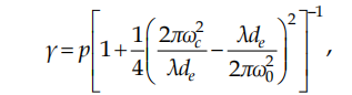
where p = Р/Рс (Pc = cε0λ2/(2πn2) is the critical power for self-focusing), ωс is the beam size in the middle of medium, and ω0 is the beam size in the waist, calculated at p = 0. The effect of “saturable absorber” requires a shrinking of the beam size with its intensity growing in the plane of the diaphragm. Quantitatively, this effect is described by a parameter (Magni et al., 1993)
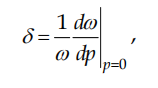
where ω is the radius of Gaussian beam in the specific plane within the cavity. To obtain the shorter pulse, parameters δ should be negative and high in modulus. The diaphragm was placed in the plane at the end-mirror М4 (see Fig. 9). The variable parameter in our simulations was the distance between the end-mirror М4 and nonlinear crystal: this distance is marked as X in our diagrams. Computations gave us a plotting for parameter δ – the graph is shown in Fig. 11. One can see from this plotting that δ takes a maximal negative value at the boundaries of stability zone. Therefore our choice for the distance was X ≈14.06 cm.
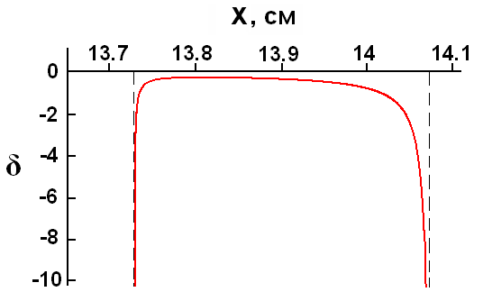
Fig. 11. Parameter δ vs. distance X. The vertical dash lines depict the boundaries of stability zone.
Fig. 12 shows the cavity’s stability zone in coordinates distance X and power p. One can see that at low power (the beginning of forming a Q-switch pulse), the laser operates at the boundary of stability zone, but when the Kerr lens has been launched, operation moves to a more stable mode.
Fig. 12. Stability zone for a resonator (grey shading). The horizontal line indicates the working distance X.
Fig. 13. Dependence of the second-harmonic output power P2ν on the DL current I for an LBO crystal at F = 2 kHz
Fig. 14. Measured autocorrelation traces of locking pulses and their sech2 fits.
When the optical correlatator for pulse registration on the two-photon-induced photocurrent in a GaAsP photodiode (type G1116, Hamamatsu) was applied for measurements, the duration of a single pulse from the Nd:YAG laser was 3.25 ps; this was at the average output power 1.5 W and the pulse repetition rate of Q-switch equal 2 kHz (the dependence of the second-harmonic output power P2ν on the DL current I for an LBO crystal at F = 2 kHz is shown on Fig. 13).
Fig. 14b demonstrates the measured autocorrelation function for a pulse. The scanning Fabry-Perot interferometer (parameters: free spectral range – 1500 GHz, reflection coefficient of mirrors – 0.96) was used for measuring the spectral bandwidth of generation Δν ≈ 200 GHz (see Fig. 15, where this spectral width was slightly increased due to contribution from instrumental broadening ≈ 10%). Therefore, we obtain Δν · Δτ ≈ 0.65, which is with accuracy to factor 2 close to the case of unchirped sech2-shaped pulses.
Fig. 15. The optical spectrum, measured with a scanning Fabry–Perot interferometer.
The peak power of a separate pulse near the maximum of envelope for Q-switch pulses was ≈50 MW. In this connection, it should be noted that Δτ was measured from the autocorrelation function at wavelength λ = 1064 nm. When we made measurements of Δτ for the Q-switch mode, it was shown that at λ = 532 nm the pulse duration was approximately twice shorter.
One might expect that this proportion in the pulse lengths will be almost the same for operating in the QLM mode, so the actual peak power of lasing may be about ≈ 100 MW.
Conclusion
In summary, we should note that ML mode of generation for a continuous laser using a travelling-wave AOM was obtained in papers (Kornienko et al., 1981; Kravtsov et al., 1983; Nadtocheev & Nanii, 1989). The authors had noted that the band of mode locking was increased by ≥ 10 times in comparison with the case of standing-wave AOM. However, in these researches the feedback was ensured using additional mirrors within the laser cavity; this made the entire design more complicated and the Q-switch mode was absent. Our solution SMAOM, when a single AOM is enough for obtaining a stable QML mode, in combination with forming a Kerr lens, will provide high levels of pulse energy ≈ 1 mJ and peak power ≈ 50 MW at least. This design of laser does not require any additional “starting” for the making of Kerr lens and it exhibits good (long-run and short-run) stability in output characteristics and there is no need in auto-adjustment schemes.