An introduction to Geometric Optics
Light Rays in Geometric Optics
A reality on this planet of Geometric Optics is that these linear light rays do not like each other: They are naturally divergent (mathematically represented as having negative vergence), trying to get away from their neighbors as fast as they can. However, if we operated with this understanding, then we could not solve any Geometric Optics problems (which you might argue is a wonderful thing), so therefore we have to make another assumption: These divergent light rays are also parallel (when originating from an extremely far away distance, which we refer to as
“infinity”), which is an assumption we will make when we solve problems, such as object–lens systems and Prentice’s Rule type of problems.
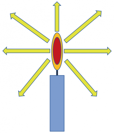
Another assumption we will make is that light rays will always travel from “left” to “right” when we draw these problems out. As seen in the candle light figure above, light travels in all directions, but for now, we will draw out most problems with light rays coming in from the left side of the diagram. However, the paths of light rays are reversible, and we will sometimes need to do this to understand why images form in a particular location, for example.
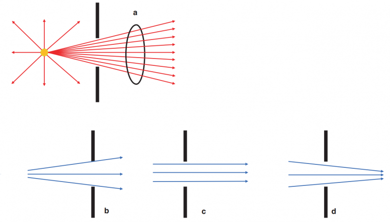
Finally, when linear light rays get affected by an external source (e.g., a plus power lens), then some of these light rays are considered to be convergent (mathematically represented as having positive vergence). For completeness, external sources may also cause parallel rays to diverge, such as when light rays pass through a minus-powered lens. We can see all three types of light rays when a pencil of light encounters an aperture (Figure below). When light rays are traveling along peacefully in a medium, they may do one of the above three actions. However, when they encounter an object, one or more things may occur:
- Refraction
- Distortion
- Dispersion
- Refection
- Absorption
- Diffraction
- Scattering
- Polarization
Refractive Index
Light rays will always travel the fastest in a vacuum (approximately 300,000,000 m/s). We can compare this speed to other common materials, such as water, aqueous, and the crystalline lens. The refractive index (n) is simply the ratio of the speed of light in a vacuum compared to the speed of light in a given material. Since light travels faster in a vacuum, n is always >1.
Refraction
Refraction simply means that when light rays pass from one medium into another medium, the original path of traveling gets bent in a different direction. Technically, there is also a change in direction in waves as they pass from one medium into another, accompanied by a change in speed and wave length of the light ray. We are simplifying this phenomenon and rebranding this as “bending of light rays”. The quality and quantity of this bending depend on several factors, such as the type of medium (index of refraction) and the surface or barrier that the light ray encounters (e.g., a converging lens vs. a diverging lens).
Snell’s Law of Refraction is a valuable tool to quantify how strongly a ray of light is refracted (bent) when passing from one material to another. In other words, this law will give us information about the angle at which an incoming light ray, after passing through the medium, exits that particular medium. Snell’s Law is defined as follows:
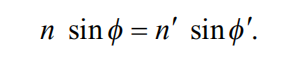
The above equation simply states that if we know
- the index of refraction of the first medium (n),
- the angle at which the light ray strikes the medium (ɸ), and
- the index of refraction of the second medium (n’),
then we can determine the angle at which the light ray will exit the medium (ɸ’). Of course, we can also solve any of the four variables used in the above equation if we have information about the other three variables.
At this point, you may be freaking out because the above equation brings back awful memories of high school geometry and scientific calculators! The good news is that you will never be asked to calculate this equation – remember that you will not be given access to a calculator for exams, so no one will ever expect you to do this trigonometry math in your head.
Instead, we can focus on the critical lessons from Snell’s Law.
One lesson is that light rays that travel from a lower refractive index medium (e.g., air, n = 1.0) into a higher refractive index
medium (e.g., water, n = 1.33) will refract (be bent) toward the norm. The norm is a man-made constructed line perpendicular to the interface between the two mediums, as seen in Figure below second lesson is that light rays that travel through a medium of higher refractive index and then encounter a medium of a lower refractive index will be bent away from the norm.
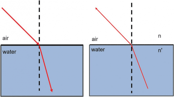
The take-home message from Snell’s Law is that with an increasing difference between two indices of refraction of two mediums, there will be an increasing amount of refraction when a light ray passes from a medium of lower index of refraction through a medium of higher index of refraction.
Refraction not only occurs throughout Geometric Optics but also has clinical relevance. Spherical eyeglasses and prisms used to quantify strabismus are two examples of refraction used in clinical practice. These topics will be discussed in greater detail in their respective sections.
Two other concepts are related to refraction: distortion and dispersion.
Distortion refers to the visual perception of an observer to refracted light rays. We can see the effects of distortion when a straw is placed in a glass of water.
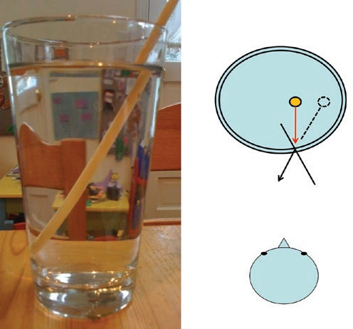
To an observer, the image of the straw above the water appears to be different than the image seen below the water. This distortion is how the observer has perceived the refraction occurring at the air–water interface.
A classic example often used in many optics textbooks is the “fisherman scenario”. The unfortunate fisherman is usually standing at the edge of a pier (or rock) with a spear (why a spear, why not a fishing rod and line or even a net like a normal person?) and sees a fish in the water. Whereas you, dear reader, may need to know optics to pass your examinations, he must rely on his knowledge of optics so that he can catch his dinner.
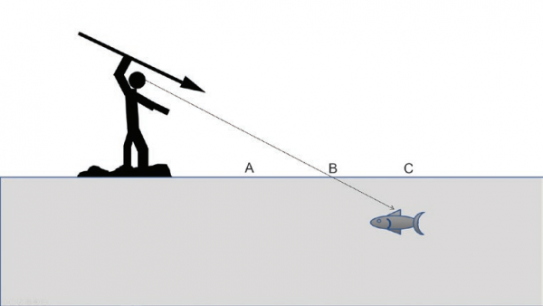
The question that is typically asked in this scenario is as follows: Where must the fisherman throw his spear to hit the fish?
This question also assumes the fisherman is a world class swimmer and diver because he then has to find his speared fish in the water, but no one ever seems to ask these important details on examinations.
Usually, you will be given several options in regards to where the fisherman should throw his spear
- In front of the fish (relative to the fisherman)—i.e., to the left of the fish (the “left” is relative to you as the reader observing the diagram) (Choice A).
- Directly at the fish—i.e., at the exact spot in the water where he sees the fish (Choice B).
- Behind the fish (relative to the fisherman)—i.e., to the right of the fish (the “right” is relative to you as the reader observing the diagram) (Choice C).
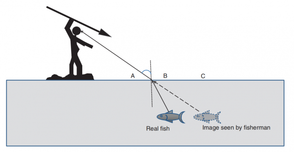
The key to solving this problem is to recall your knowledge of the previous discussion. Since light rays emanating from the fish will strike the water–air interface, they are going from a medium of higher refractive index into one with a lower refractive index. Since these light rays will refract (bend) away from the normal, for the fisherman, the actual fish will be “in front” (i.e., to the left to you as the reader looking at the diagram) of where he is “seeing it”.
Therefore, if he wants to catch his dinner, he must use this knowledge of optics and throw his spear at point A.
He should also tie a rope to his spear so that it is easily retrievable from the water without diving into the lake.
Technically, distortion is a subset of optical aberrations, which will be discussed later, but it may be helpful to under stand some elementary principles of this concept under the discussion of refraction.
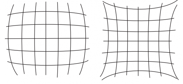
One clinically relevant area (also relevant for test purposes) is the concept of barrel distortion and pincushion distortion, which occur with minus lenses and plus lenses, respectively. You can remember this with the mnemonic plus lens = p in cushion distortion. We will discuss the differences between plus and minus lenses later, but for now, you should know that the edge of a plus or minus lens is very different from the optical center of the lens.
Specifically, a minus lens is much thicker at the edges (compared to the center), and a plus lens is much thinner at the edges (compared to the center). Therefore, light rays that pass through the edge of each of these lenses will be refracted differently than light rays that pass through the center of the lens.
For minus lenses, because the edge of the lens is thicker than the center, image magnification will decrease further away from the optical center, such that the image at the edge of a minus lens will appear to have been “wrapped” around a sphere or a barrel (“barrel distortion”).
For plus lenses, image magnification will increase further away from the optical center, such that the image of the edge of a plus lens will appear to be stretched out toward the periphery We will discuss this topic in greater detail in the section on troubleshooting glasses in patients.
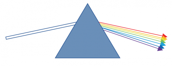
Dispersion occurs whenever light rays undergo refraction. Specifically, dispersion refers to the change in the angle of refraction of the individual colors of light that comprises a white light ray. The frequency of a given component of the light ray will determine how much dispersion occurs—the higher the frequency, the more dispersion of that particular color will occur.
For example, blue light, which has the highest frequency (and therefore the lowest wavelength), under goes the most refraction (bending), whereas red light undergoes the least. A useful mnemonic to remember is that blue light rays will get bent the most, whereas red light rays are rarely bent.
If blue text and red text are both placed against a dark or black background, then an interesting phenomenon known as chromostereopsis occurs. This visual illusion causes the brain to perceive depth when viewing a two-dimensional color image, usually blue-red images. Chromatic aberration effects will cause the brain to view the red portion of the text/image as “closer” to you as the observer than the blue.
Remember that the “red” rays normally land “behind” the retina, and the “blue” rays normally land “in front of” the retina. Since we have to accommodate (generate plus power) in order to see any red text (since usually, those light rays will fall behind the retina), when both red and blue text are placed side by side, the brain will have to accommodate in order to see the red and then relax accommodation to see the blue text. As a result, the brain will falsely think that the red text is closer than the blue text!
Every material has an amount of dispersion known as the Abbe number (aka the V-number). The higher the Abbe number, the lower the chromatic aberration in that particular material and vice versa. Chromatic aberration has clinical relevance when discussing the construction of glasses. For example, it is advantageous to use lens materials with high Abbe number values to minimize the adverse effects of chromatic aberration.
Reflection
We can begin our discussion on refection by first introducing this concept with a plano (fat, not curved) mirror, such as the one you used this morning while brushing your teeth and preparing yourself to study Geometric Optics.
In a plano mirror, every single incoming light ray is “bounced back” away from the mirror’s surface; none of the incoming light rays are “refracting” through the mirror (and into the wall).
Think of refection as the term used to describe how some incoming light rays will bounce back from the optical interface.
As discussed in the previous section, some light rays will be refracted when they encounter an optical interface.
However, some of the light rays will also be reflected, as in the case of the plano mirror. We can be a bit more sophisticated than simply stating refection is the “bouncing” back action of incoming light rays: refection refers to the change in direction of light rays such that the angle at which incident light rays approach a medium will equal the angle at which they reflect away from the medium. The second medium is essentially a barrier through which light rays can not penetrate.
In other words, when light rays approach a barrier and instead of passing through (refraction), they bounce off the barrier (refection). Depending on the barrier’s geometry reflected light rays from opposite angles will then converge at a single location known as the focal point.
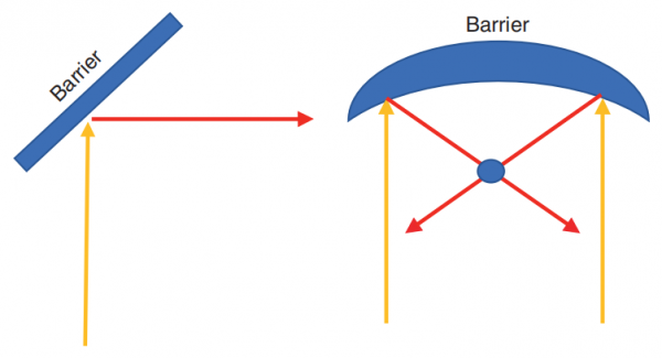
Furthermore, there are two different types of refection that you may wish to know. Specular refection is when light reflects in a single direction (as seen in clinical practice when using specular refection as an illumination strategy during slit-lamp examination), and diffuse refection, wherein light reflects in many directions off a given barrier.
The law of reflection states that the incident ray (incoming ray) and the reflected ray (outgoing ray) will lie in the same plane as the surface normal, which means both rays will have the same angle with respect to the surface normal (Fig. below). We can compare the angle of refection to the previously discussed angle of refraction (transmission).
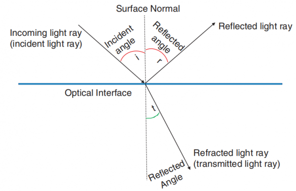
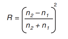
Why do we care about this? The amount of light reflected from a surface is related to the incoming angle and the two media. We can use the refection coefficient to calculate the amount of light transmitted at an optical interface during refection as follows (equation. below)
Critical Angle and Total Internal Refection
When light rays encounter a barrier, both refraction and refection will occur, based on the incident angle at which a given light ray approaches the barrier. When considering light rays that pass from a medium with higher index of refraction (e.g., water) into a medium with lower index of refraction (e.g., air), the concept of the critical angle states that when incident light rays approach a barrier at any angle less than the critical angle, these light rays will get refracted—i.e., they will pass through the medium, get bent, and emerge on the other side. When incident light rays approach a barrier at any angle greater than the critical angle, these light rays will get reflected—i.e., they will not pass through the medium and instead will be bent back into the original medium (Fig. below).
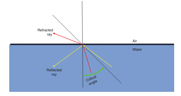
For the sake of completion, an incident light ray that approaches the interface with an angle that equals the critical angle will neither get refracted nor get reflected, but instead will undergo absorption (which is energy lost as heat, which is negligible for the purposes of Ophthalmic Optics and you should not waste brain cells on this any further).
Every material has its respective angle that is unique for that material. You may wish to memorize that ordinary glass has a critical angle of 41 degrees, but do not waste time knowing the values of various critical angles for different media.
Let us use a silly metaphor to drive this home further.
Think of light rays as a bunch of senior high school students attempting to have a class ditch day. Those students who can approach the school exits and avoid detection by the hallway monitors at less than the critical angle will be able to escape (i.e., refraction occurs). However, those students who approach at an angle that the hallway monitors can see them will not be able to escape and will be made to stay in the school (i.e., refection occurs).
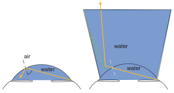
Where is this clinically relevant? In clinical examination of the anterior chamber angle for most eyes (i.e., excluding pathologic myopes, megalocorneas, or ectatic corneas), it is impossible to visualize the anterior chamber angle because light rays that emerge from the angle are greater than the critical angle. These light rays are not refracted and instead undergo total internal refection and are reflected into the anterior chamber at the air–tear film interface.
Gonioscopy allows us to bypass the tear film–air (1.33–1.00) interface that the emerging light rays from the anterior chamber angle cannot penetrate by creating a “water–water interface (1.33–1.33; the lens also has an index of refraction, but for our discussion we can ignore it) when the lens is placed on the cornea (Fig. below). Light rays from the angle are no longer reflected and instead *refracted* at this new inter face, thereby reaching the examiner’s eye and allowing for examination of the anterior chamber angle structures.
For bonus points, you may wish to memorize that the critical angle between air and aqueous is approximately 48.6°.
Total internal refection is all around us—it is used in fiber-optic cables, binoculars, and even the slit-lamp. You cannot escape optics no matter how much you try.