Research and Application of Terahertz Imaging Technology
terahertz, time-domain spectroscopy, microbolometer, imaging technology
Abstract
Terahertz (THz) waves are located between the infrared and microwave bands. Compared with other bands, they have the characteristics of high transmission, low energy, coherence and transient nature. With the widespread application of terahertz imaging technology in the fields of space communication, radar detection, aerospace and biomedicine, it has been shown that THz imaging offers advantages over traditional imaging technologies (such as ultrasonic imaging and X-ray imaging).
This paper first introduces the development status of THz time-domain spectroscopy (THz-TDS) imaging technology and room temperature (uncooled) microbolometer THz imaging technology. Subsequently, typical applications of THz imaging technology are presented. Finally, the limiting factors of THz imaging technology are discussed.
Introduction
Terahertz waves refer to electromagnetic waves with a frequency in the range of 0.1 to 10 TH (z 1 THz = 1012 Hz).
Terahertz technology is a technology to study the generation, detection and application of terahertz waves. Terahertz imaging technology is an emerging cutting-edge interdisciplinary science and technology, involving the fields of physics, materials science, chemistry, and engineering technology.
Terahertz imaging technology uses terahertz pulses to act on the target, not only through the target imaging, but also by obtaining information such as the intensity and phase of the terahertz pulse reflected by the target, and then realizing terahertz imaging through digital signal processing and spectrum analysis.
This paper reviews the development status of terahertz time domain spectroscopy (THz-TDS, terahertz time domain spectroscopy) imaging technology and uncooled microbolometer terahertz imaging technology, then introduce the application of terahertz imaging technology in national security, safety inspection, biomedicine and environmental monitoring, etc., and finally analyze the influencing factors in the development of terahertz imaging technology.
1 Terahertz time-domain spectral imaging technology
With the rapid development of information technology, THz-TDS imaging technology has shown broad application prospects in engineering (such as resource exploration and food processing), high-speed communication, astronomical research, and biomedicine. More and more countries and scientific research units have begun to conduct in-depth research on THz-TDS imaging technology, and have obtained high-signal-to-noise ratio, high-resolution images to meet the application requirements of different fields.
1.1 Terahertz pulse scanning imaging
Terahertz pulse scanning imaging uses terahertz pulse signals to scan the target object placed on the two-dimensional scanning translation stage point by point.
The target moves on the X-Y plane perpendicular to the transmission direction of the terahertz wave. The pulse signal passes through different positions of the target, records the transmission information or reflection information at different positions, and obtains the time-domain waveform of each pixel point. The technology extracts information such as phase and amplitude contained in the frequency spectrum, and constructs an image of the target object through frequency spectrum analysis.
Terahertz pulse imaging has the advantage of high signal-to-noise ratio, and its resolution can reach submillimeter level. The earliest AT&T, Bell Laboratory and IBM obtained broadband terahertz pulses through photoconduction or photorectification.
With the advancement of technology, the focused femtosecond laser is used to ionize the air at the focal point to form air plasma, and the optical nonlinear effect can also be used to generate terahertz pulses.
Figure 1(a) is the THz wave generated by the photoconductive method, (b) is the THz wave generated by the photorectification effect, and (c) is the THz radiation generated by the air plasma effect.
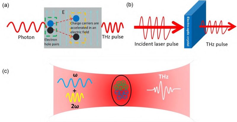
Fig.1 (a) Photo conductance effect; (b) Optical rectification effect; (c) Air plasma effect
In 1995, B. Hu et al. used an 800 nm pulsed laser to scan and image the leaves point by point, and extracted the phase and amplitude information of the sample through the speech recognition algorithm. The specific optical path diagram of the system is shown in Figure 2, and the experimental results are shown in Figure 3. The color depth in the image reflects the water content, and the darker the color, the more water content.
Fig. 2 Schematic diagram of transmission THz imaging system
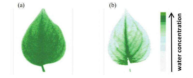
Fig.3 The leaves were scanned and imaged using a transmissive THz imaging system: (a) Fresh leaves; (b) Leaves after 48 hours
Since the system does not use a lock-in amplifier (LIA), the signal-to-noise ratio is low. In order to improve the signal-to-noise ratio, in 1997-2001, T. Dorney et al. developed a reflective terahertz imaging system, which effectively suppressed the background noise through an interferometer device with phase conversion, and greatly improved the signal-to-noise ratio and depth resolution.
Experimental results show that the resolution capability of the system can reach 2% of the resolving coherence length. In 2008, D. Banerjee et al. used terahertz pulse scanning imaging to detect the moisture content in paper.
Since terahertz radiation is more sensitive to subtle changes in moisture in paper, it is not sensitive to fiber scattering, and high measurement accuracy can be achieved by using this characteristic.
In 1996, Zhang and others from Rensselaer University in the United States developed a pulsed focal plane imaging system, which improved the signal-to-noise ratio of terahertz imaging and expanded the application range of terahertz imaging. Later, Zhang et al. used dynamic subtraction technology to modulate the output frequency of the signal with a chopper, combined with CCD synchronous control, which effectively reduced the influence of background noise and enhanced the value of pulsed focal plane imaging in practical applications.
In 2006, Zhong et al. performed spectroscopic detection of various chemical species by a reflective terahertz pulsed focal plane imaging system. The system uses a reflection measurement mode, which improves the practical performance of the imaging system.
Due to the time-consuming problem of terahertz pulse imaging, too long time will have a great impact on the imaging quality. Yasui et al. from Osaka University in Japan improved the terahertz imaging system and developed a pulse focal line imaging system. The schematic diagram of its optical path is shown in Figure 4(a).
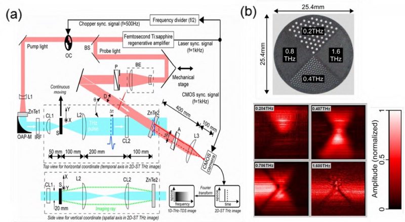
Fig.4 Terahertz imaging system and terahertz images of samples: (a) THz pulse focal imaging system; (b) THz images of metal hole array samples and samples at 0.204 THz, 0.407 THz, 0.815 THz, 1.600 THz
The terahertz wave converges into a focal line through the cylindrical lens (CL1) and irradiates the sample. After passing through the sample, the terahertz focal line passes through a ball lens (L2) and another cylindrical lens. The lens (CL2) is collimated into parallel light. In the detection optical path, the detection light first undergoes beam expansion, and forms non-collinear coincidence with the terahertz beam.
Different overlapping regions correspond to different time delays. In the overlapping area, the detection light and the detection crystal are kept relatively vertical, and the detection crystal performs photoelectric sampling for the terahertz signal.
Therefore, using this imaging technology does not require time-domain scanning of the terahertz signal, and the terahertz time-domain signal can be directly extracted from the image acquired by the CMOS camera, greatly reducing the time-consuming experiment. Yasui et al. used this system to perform an imaging test on a metal hole array sample. The sample is divided into 4 regions, and the hole array size is different in each region, and the sample moves laterally through the terahertz focal line at a moving speed of 1 mm/s. Figure 4(b) shows the THz images of the samples at 0.204 THz, 0.407 THz, 0.815 THz, and 1.600 THz.
In addition, due to the use of CMOS cameras to collect terahertz images, phase-locking filtering cannot be performed, resulting in a low signal-to-noise ratio of terahertz signals. In 2010, Schirmer et al. used terahertz pulse focal line imaging technology to detect tissues such as teeth, and experiments proved that this system has good results in biological detection. In 2011, Blanchard et al. increased the image resolution of terahertz pulse focal plane imaging to 14 μm, reaching 1/30 of the corresponding terahertz wavelength (430 μm, 0.7 THz), and realized terahertz near-field microscopy.
The system uses quasi-near-field detection and differential electro-optic detection measurement methods, and the special feature is that the detection crystal used is a LiNbO3 crystal with a thickness of 20 μm. LiNbO3 has a strong electro-optic coefficient and can respond sensitively to terahertz pulse signals. This work shows that the pulsed focal plane imaging system can detect micron-sized samples, which greatly expands the application field of terahertz imaging technology.
1.2 Terahertz real-time imaging
The terahertz real-time focal plane imaging system belongs to the reflective terahertz imaging system.
The system can obtain the spectral information of the entire object to be measured without two-dimensional scanning of the object to be measured, which can reduce the adverse effects caused by the long time of terahertz point-by-point imaging. Figure 5 shows the terahertz real-time focal plane imaging system based on electro-optic materials developed by Zhang and Nick et al.
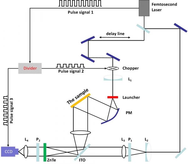
Fig. 5 THz real-time focal plane imaging system
The electro-optic crystal sampling measurement technology can directly observe the two-dimensional intensity distribution of the terahertz electric field without the photothermal effect and photon effect. Although the system response time is short, the defects of the electro-optic crystal will affect the imaging quality.
In order to detect the cause of the Columbia space shuttle crash, Zhang et al. built the first miniaturized and portable terahertz continuous wave imaging system.
Compared with scanning imaging, this system can increase the speed of information extraction. Experiments have shown that terahertz imaging technology has excellent performance in non-destructive testing, which is unmatched by X-rays and ultrasonic waves.
In order to further eliminate the influence of the defects of the photodetection crystal material itself on imaging and improve the performance of terahertz real-time imaging, in 2007 Hattori et al. used a data processing method to detect the inhomogeneous optical properties of the crystal itself in terahertz real-time imaging. And the image distortion caused by light wave scattering is extracted separately, and the factors that cause these effects are eliminated, which can further optimize the quality of terahertz real-time imaging.
Later, Yasuda et al. used terahertz real-time imaging technology to image water droplets in water pipes and small iron nails in plastic bags, combined with a CMOS camera to clearly observe the movement of objects.
In addition, in order to study the diffraction process of terahertz pulses in crystals, Nelson et al. designed a new type of terahertz real-time imaging system. By placing the object to be measured in a LiNbO3 crystal, the femtosecond laser fundamental frequency light and frequency doubled The light irradiates LiNbO3 crystal together, the fundamental frequency light is used to generate terahertz pulse, the double frequency light is used to detect terahertz pulse, and the diffraction process of terahertz pulse in LiNbO3 crystal is observed.
In 2009, British company Thru Vision developed a passive focal plane imaging system with a multi-channel heterodyne receiving array, which enables the imaging distance to be greater than 20 m and the frame rate to be higher than 10 Hz, which can be used for vehicle-mounted imaging. It is the first terahertz passive detection system put into use in security inspection.
In 2013, Han et al reported an InGaAs-based Schottky barrier diode (SBD) array detector, which can be used for terahertz real-time imaging, with an average responsivity of 98.5 V/W and NEP≈10-10W/Hz1/2.
In China, Y. Jun et al. from Shenzhen University carried out 1.89 THz imaging research for the first time through pyroelectric focal plane array PY-III.
Since then, Harbin Institute of Technology has developed a terahertz real-time imaging system through the combination of pyroelectric focal plane array PY-III and SIFIR50 CO2 gas terahertz laser, which perform terahertz imaging at frequencies of 1.63 THz, 2.45 THz and 2.52 THz respectively. Transmission imaging resolution reaches 0.6 mm. This system has the characteristics of low power consumption, low cost, and good imaging quality, but the detection sensitivity is low, and a chopper is needed as an auxiliary.
1.3 Terahertz near-field imaging
Since terahertz waves belong to far-infrared radiation, it can be known from the Rayleigh criterion that terahertz imaging is limited by the diffraction limit corresponding to the wavelength, and the resolution is lower than that of visible light, which cannot meet the requirements of high-precision measurement.
For traditional terahertz point-by-point imaging systems and real-time imaging systems, the imaging resolution is generally on the submillimeter level, which limits the practicability of terahertz imaging technology and the resolution of terahertz imaging systems, so it is necessary to break through the diffraction limit of.
To this end, a terahertz near-field imaging technology is proposed, which greatly improves the performance of terahertz imaging. Figure 6 shows a terahertz pulsed near-field scanning imaging system. The so-called terahertz near-field imaging technology usually refers to terahertz scanning near-field optical microscopy (THz scanning near field optical microscopy, THz-SNOM) technology.
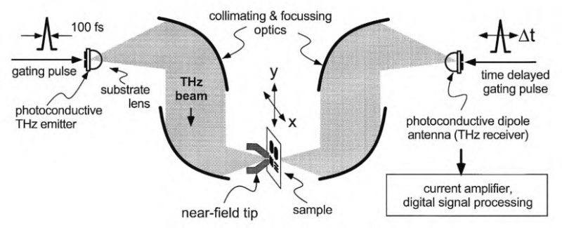
Fig.6 THz pulse near-field scan imaging system
The development of terahertz near-field imaging technology mainly includes the following types: THz-SNOMs based on scattering, THz-SNOMs based on aperture, and THz-SNOMs based on time-domain spectroscopy.
This part mainly summarizes the research on scattering THz-SNOMs technology. Huber et al. used an atomic force microscope (AFM) to study the THz-SNOMs technique for far-field detection of backscattered signals.
Near-field microscopic imaging of semiconductor transistors at 2.52 THz was performed using a terahertz laser, and an image with a spatial resolution of about 40 mm was obtained. In 2012, Moon et al. developed a diffuse THz-SNOMs system by using a photoconductive antenna as a terahertz source, and successfully obtained near-field signals. After scanning and imaging the metal flakes on the Si substrate, an image with a spatial resolution of about 200 nm is obtained.
In 2016, Dean et al. of the University of Leeds in the UK used quantum cascade lasers (quantum cascade lasers, QCLs) as laser sources, and used probe technology to detect near-field scattering signals by self-mixing, and obtained a spatial resolution of 1 μm. image. Later, Kuschewski et al. used a high-power free-electron laser (Free-electron laser, FEL) as a radiation source to detect and identify metal nanoparticles in the 1.3-8.5 THz frequency band, and obtained microscopic images with a spatial resolution of 50 nm. .
In 2017, Degl and others at the Cavendish Laboratory of the University of Cambridge also used QCL as a radiation source and self-mixing to detect signals, controlled the vibration of metal nanoprobes through quartz tuning forks, and plasmon resonance antennas Scattering near-field imaging of the structure was performed with a spatial resolution of 78 nm.
In 2018, Liewald et al. used a Schottky diode (SBD) with a frequency of 0.5-0.75 THz as a pump source to develop a scattering THz-SNOMs system, which uses heterodyne detection technology to obtain the phase and amplitude of near-field signals . By characterizing the semiconductor carriers, a terahertz near-field image with a spatial resolution of about 50 nm is obtained.
Most of the above-mentioned THz-SNOMs systems use gas lasers, photoconductive antennas or QCLs as emission sources, and have not achieved nanoscale resolution in the millimeter wave band.
You Guanjun and others from University of Shanghai for Science and Technology cooperated with Fritz Keilmann, the pioneer of SNOMs technology, to carry out research on terahertz SNOMs technology using QCL as light source.
In 2016, the first self-developed scattering THz-SNOMs system in China was built. This system adopts high-order demodulation background compression technology, which can effectively extract scattered near-field signals, and can still maintain extremely high spatial resolution while obtaining high spatial resolution. signal-to-noise ratio. After that, by using the terahertz frequency doubling module in the 0.1-0.3 THz frequency band as the emission source, a scattering THz-SNOMs system with a nanoscale spatial resolution was developed.
The system converts the evanescent waves on the sample surface into far-field radiation waves through nanoprobes, and then obtains terahertz near-field images through the point-by-point scanning technology of the probes.
Experiments show that the scattering THz-SNOMs system images the metal film of the Si substrate at frequencies of 196 GHz and 276 GHz respectively, and images with a spatial resolution of less than 60 nm are obtained. Figure 7 shows the scattering THz-SNOMs system Schematic diagram of the experimental setup and system.
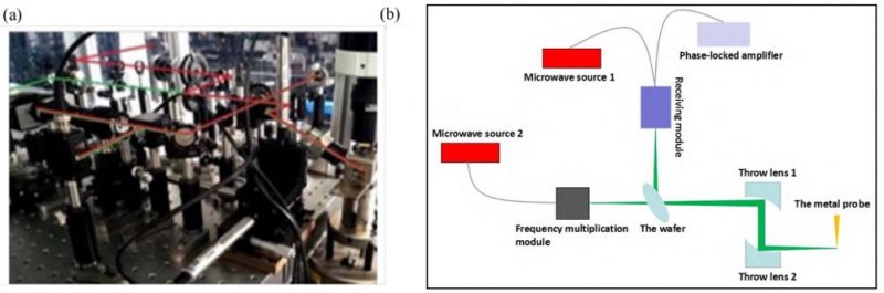
Fig.7 Scattering THz-SNOMs system with high spatial resolution: (a) Photos of experimental apparatus and (b) System principle
1.4 Terahertz Confocal Scanning Imaging
Terahertz confocal scanning imaging has the advantages of terahertz imaging and laser confocal scanning imaging, and can be divided into reflection type and transmission type according to the imaging method.
In 2006, German Salhi M. A. et al. realized the semi-confocal transmission scanning microscope for the first time, and Fig. 8(a) is the light path diagram of the semi-confocal transmission scanning.
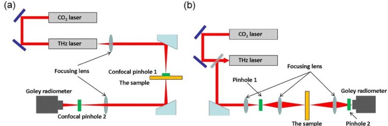
Fig.8 Confocal scanning imaging system: (a) Transmission type semi-confocal scanning and (b) Confocal scanning imaging system
However, in a semi-confocal setup, the imaging size is limited because the sample is placed directly behind the pinhole.
Later, Salhi M. A. designed a transmission confocal scanning imaging system on the basis of the semi-confocal scanning microscopy imaging system. The far-infrared gas laser was pumped to generate 2.52 THz laser, and its spatial resolution could reach 0.26 mm. Fig. 8(b) is a transmission confocal scanning imaging system.
In 2009, Salhi M. A. et al. improved the semi-confocal scanning microscopy imaging system and designed the size of the detection pinhole to be 0.5 mm. The experiment showed that the spatial resolution was further improved after adding the pinhole, making the confocal imaging resolution higher than that of ordinary optical system.
In 2008, Zinovev N. N. et al. developed a transmission terahertz imaging experimental device system. The photoconductive antenna is excited by a femtosecond laser to generate terahertz radiation. The sample is a grating array composed of a Cr layer coated on a Si substrate. The terahertz pulse waveform and spectrum of the sample were obtained through experiments, but the addition of pinholes did not change the frequency component of the terahertz pulse. Later, Lim M. et al. in South Korea proposed a terahertz reflective confocal scanning microscopy imaging system, which includes a terahertz source, a beam splitter, a lens, a detector, and copper pinholes.
The terahertz wavelength used in the system is 0.3 mm. The three lenses play the role of collimator, objective lens and collecting mirror respectively. The pinhole is placed at the focal plane of the collecting mirror. After calculation, the imaging resolution can reach 40 μm. In order to further obtain terahertz radiation information, in 2012, R. U. Siciliani de Cumis et al. developed a QCL confocal microscopy imaging system, which uses a lens that can highly transmit terahertz radiation, which can better collimate and collect terahertz radiation information .
In 2014, Hwang et al. developed a transmission imaging experimental device for free electron laser pulses, which allowed the frequency of terahertz radiation to reach 2.7 THz, and observed the skin of living mice, and found that cells have good dynamic responses to terahertz radiation.
Domestic terahertz confocal scanning imaging is in its infancy, and there are few related research results. At present, the research units mainly include University of Electronic Science and Technology of China, Capital Normal University and Harbin Institute of Technology.
In 2008, Zhang Yandong of Capital Normal University and others used coherent detection technology to obtain terahertz reflective confocal scanning microscopy imaging. The system uses a Gunn oscillator to generate 0.2 THz radiation, a pinhole size of 2 mm, and an axial resolution of 25.5 mm.
Due to the larger pinhole size and longer wavelength, the imaging resolution is lower. In order to solve the above problems, in 2010, Ding Shenghui of Harbin Institute of Technology and others developed a transmission confocal scanning microscopy imaging system through the CO2 pumped continuous terahertz laser of SIFIR-50.
The detector is a P4-42 pyroelectric detector, and the pinhole at the light source and the detection pinhole are 1.2mm and 0.6mm respectively. Experiments have proved that the lateral resolution of the obtained image has been significantly improved, and the tiny area of the metal sheet smaller than 0.25 mm can also be imaged.
In 2011, Di Zhigang of Tianjin University and others developed a continuous scanning terahertz imaging system. The light source used in terahertz is FIRL-100, which produces 2.52 THz radiation, and the detector uses LiO3Ta pyroelectric detector. The experimental results show that the lateral resolution of the system is less than 0.5 mm, and a higher spatial resolution is obtained.
1.5 Terahertz 3D Imaging
Since terahertz three-dimensional imaging technology can better obtain the information inside the sample, it has gradually become a research hotspot.
Terahertz three-dimensional imaging technologies mainly include terahertz computer-aided tomography (CT) imaging, terahertz diffraction tomography, terahertz tomography, and terahertz digital holography.
At present, terahertz CT imaging is relatively mature in the use of terahertz three-dimensional imaging technology. To evaluate the performance of a terahertz 3D imaging system, the detection distance is a very important evaluation index. In 2006, the US Jet Propulsion Laboratory (JPL) developed a THz radar imaging system with high-resolution ranging capabilities.
When the target distance is 4 m, the one-dimensional ranging resolution reaches about 2 cm. Afterwards, the JPL laboratory in the United States successfully realized 3D imaging at 25m by means of frequency modulation in the 662-691GHz frequency band, with a plane resolution of 1 cm and a depth resolution of 7mm.
In order to further improve the detection distance, in 2008, the Fraunhofer-Gesellschaft (Fraunhofer-Gesellschaft) successfully achieved a two-dimensional detection at a distance of 200 m at 0.220 THz by using a technology combining frequency-modulated continuous wave (FMCW) and inverse aperture radar. Imaging to achieve a resolution of around 1.8 cm. In 2009, the Pacific Northwest National Laboratory (PNNL) in the United States realized three-dimensional imaging at a distance of 5 m from the target object, using a frequency of 345.2-354.8 GHz, the resolution is 1.5 cm, and the imaging time is 10 s for a field of view of 3 m².
In 2009, the German RPG company realized three-dimensional imaging at a detection distance of about 1.5 m by using FMCW technology in the frequency range of 230-320 GHz, with a depth resolution of 1.4 mm and a plane resolution of 4 mm at a distance of 0.5 m. The imaging time for a field of view of 20 cm is about 9 s (75×50 pixels). Later, Brahm A. et al. used THz-TDS imaging technology to perform spectral tomography imaging of polystyrene foam filled with glucose and lactose, and then compared with the database to identify the location of glucose and lactose in the material.
In 2014, Brahm A. used THz-TDS imaging technology to conduct in-depth research on the optical effects of CT projection on samples of different materials and shapes. Combined with Zemax software to simulate the projection image, the experimental results show that the obtained refraction effect is in good agreement with the theoretical calculation.
In 2010, Kato E. from Japan excited the photoconductive switch through an ultrashort-pulse fiber laser to generate a 3 THz pulse signal to realize spectral three-dimensional tomographic analysis. The characteristic of this system is that it uses a fiber laser and a photoconductive switch to generate terahertz waves, which can detect the amplitude and phase projection information in the entire frequency band. Figure 9(a) is the schematic diagram of the three-dimensional spectral tomography experimental device, and (b) is the experimental result.
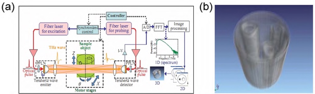
Fig.9 Three-dimensional spectrum chromatography system and its imaging results:(a) Schematic diagram and (b) Experimental results
In the same year, Buma T. et al realized the construction of a three-dimensional image of the target by combining the synthetic aperture focusing technology with the point-by-point imaging technology. In addition, they used a weighted sum algorithm to solve the problem of side lobe artifacts in the reconstructed image. Abraham et al. studied the effect of objects with a large refractive index on 3D tomography by terahertz pulse imaging.
In 2012, the University of St. Andrew designed a 0.34 THz superheterodyne three-dimensional imaging radar system, which is used for display and processing by transmitting co-polarization, receiving co-polarization, and cross-polarization. This project started in 2008, and through continuous improvement, an imaging frame rate of 10 frames/s was obtained at 20 m.
In 2012, the University of St. Andrew designed a 0.34 THz superheterodyne three-dimensional imaging radar system, which is used for display and processing by transmitting co-polarization, receiving co-polarization, and cross-polarization. This project started in 2008, and through continuous improvement, an imaging frame rate of 10 frames/s was obtained at 20 m.
In 2016, S. Tripathi et al. converted the detection technology of narrow linewidth, tunable terahertz parametric source and terahertz conversion frequency for CT imaging of plastic objects, because this method converts the detection of terahertz frequency to near-infrared band , the detection dynamic range can reach 90 dB around 1.5 THz, which can well reflect the internal information of the object and the location of the defect. In 2017, Zhou Tao et al. used uni-traveling-carrier photo diode (UTC-PD) to generate 90-140 GHz low-coherence terahertz radiation, and successfully reconstructed the three-dimensional image of ceramic samples, showing that terahertz Waves have great practical value in nondestructive testing.
1.6 Terahertz differential imaging and polarization imaging
In THz-TDS technology, the stability, accuracy and signal-to-noise ratio of terahertz pulses can be further improved by using differential detection technology. Since the differential detection technology does not use orthogonal polarizers, the dynamic subtraction technology is used to effectively suppress the noise signal and improve the strength of the detection signal.
In 2004, Hattori T and Rungsawang R and others improved the linearity of measurement by using terahertz real-time imaging optical heterodyne detection technology, but the signal-to-noise ratio is low, which is not ideal.
In 2007, Pradarutti et al. designed an imaging system that basically realized differential imaging, but due to the small number of pixels, real-time imaging could not be performed. Kitahara et al. successfully achieved differential imaging of adjacent pixels by combining a 1/4 wave plate, a CMOS camera, and a linear array polarizer.
In 2010, Wiegand et al. line-focused the terahertz wave and the detection wave respectively, and realized terahertz differential imaging by using two linear array CMOS cameras combined with differential detection technology. The system uses a laser light source with an oscillator, which improves the integrability of the terahertz real-time imaging system.
In terahertz imaging technology, most methods of photoconductive sampling and electro-optic sampling are used to measure terahertz pulses, basically ignoring the polarization factor existing therein. In order to improve the information acquisition capability of the imaging system, high-precision measurement of different terahertz polarization components can be achieved by changing the polarization state of the probe light.
In 2005, Planken et al. developed a new optical detection technology and realized the measurement of the terahertz polarization state. For the optical path system diagram, refer to the literature.
In 2006, Rutz et al. used THz-TDS imaging technology to measure the birefringence properties of liquid crystal polymers, and used terahertz point-by-point imaging technology to detect the change of the optical axis direction in the sample, but this technology did not observe The condition of the interior of the sample.
In 2009, Jordens et al. adopted a new data processing method, using the spectral characteristics of terahertz time-domain pulses, to observe that the distribution inside the sample presents anisotropy.
In 2010, L. Zhang et al. used quartz crystals as polarizers. Due to the different time delays of quartz crystals for terahertz polarization components, the polarization information of samples can be extracted, and the polarization information of foam was measured by this method.
In China, Zhang Yan’s team, which has conducted in-depth research on terahertz differential imaging and polarization imaging, introduced the following two technologies in order to improve the signal-to-noise ratio of the imaging system and the information acquisition ability of the imaging system:
- Introduce the differential electro-optic detection technology into the imaging system, so that the signal-to-noise ratio of the single-pixel terahertz signal can reach 20 dB;
- The high-precision measurement of different terahertz polarization components is achieved by changing the polarization state of the probe light, which improves the detection sensitivity and accuracy. Figure 10 shows the improvement of the team’s terahertz pulse focal plane imaging system.
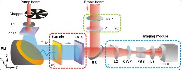
Fig.10 Improvement of THz pulsed focal plane array imaging system
1.7 Research on other terahertz imaging technologies
With the development of science and technology, terahertz imaging technology has made great progress, and many key technologies have been broken through, so that the resolution, sensitivity, response frequency bandwidth and response time of terahertz imaging have been continuously improved.
The following introduces some representative frontier research on terahertz imaging technology, which shows the rapid development of terahertz imaging technology.
In 2007, the University of Frankfurt in Germany developed the Hybrid system, which can divide continuous terahertz waves into two beams, one of which is used to detect objects, and the other does not carry any information and is only used as a reference. High-resolution continuous terahertz imaging can be achieved by comparing two beams of terahertz waves.
In 2010, Korea Lee K and others studied the imaging method of terahertz compressive sensing theory (Compress sensing, CS) based on coherent optics. CS theory is mainly used for signal analysis. It exploits the sparse characteristics of the signal, and obtains discrete samples of the signal by random sampling under the condition of far less than the Nyquist sampling rate, and then reconstructs the signal through a nonlinear algorithm. At present, it has received extensive attention in the fields of optics, information processing, microwave imaging, and pattern recognition.
In 2011, Yu et al. from Harvard University proposed the concept of metasurface for the first time, and developed a subwavelength metal antenna device, which has a special modulation effect on the visible light field.
In 2012, Han et al. successfully realized electronic multi-pixel scanning imaging with a responsivity of 5.1 kV/ W, NEP = 2.9×10⁻¹¹W/Hz1/2. SBD THz has the characteristics of fast response, high sensitivity, and room temperature operation, but the parasitic capacitance will affect the device performance when operating at high frequency.
In 2015, Huang Zhiming, a researcher at Shanghai Institute of Technical Physics (SITP), Chinese Academy of Sciences, successfully realized a 0.3-3.0 THz wide-band, high-sensitivity, low-noise-equivalent Hertz detection device, and proved the feasibility of high-sensitivity terahertz detection by generating a new type of photoelectric effect through photon fluctuations. This work provides an important technical approach for the breakthrough of terahertz detection technology. The schematic diagram of the detector is shown in Fig. 11.
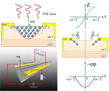
Fig.11 Schematic diagram of a THz detector based on narrow bandgap semiconductors
In 2017, Wu Fuwei et al. studied the terahertz SAR imaging radar in the 220 GHz band. Figure 12 is a diagram of the terahertz SAR imaging radar system.
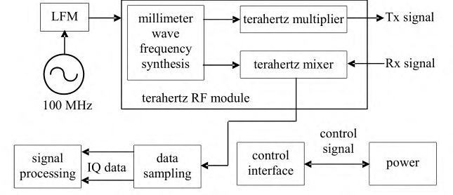
Fig.12 THz SAR imaging radar system
The experimental results show that the resolution of the terahertz SAR imaging radar system can reach 3 cm. Experiments show that the terahertz SAR imaging radar system has stronger penetration ability than the photoelectric sensor, and its imaging speed is also better than the traditional microwave radar.
In 2017, Liu Liyuan and others developed a THz imaging system based on CMOS technology combined with low-noise signal processing technology. The system uses a terahertz antenna, a high-voltage response transistor, and a THz matching network. At room temperature, the system has high image resolution and imaging quality, and NEP<1.06×10⁻¹⁰W/Hz1/2.
In 2019, Lu Yuanfu’s team proposed and realized a new terahertz single-pixel imaging technology based on spatial Fourier spectrum.
By using a spatial light modulator (digital micromirror device, DMD) to generate sinusoidal fringes to modulate the terahertz beam incident on the silicon-based graphene, and then the terahertz single-pixel detector acquires the spatial Fourier spectrum of the two-dimensional image of the object, Finally, the two-dimensional image of the imaging target is reconstructed by inverse Fourier transform.
The experimental results show that this method can greatly reduce the number of measurements and improve the imaging efficiency under the premise of ensuring the image quality. The number of measurements only needs 11.8% of the number of image pixels to reconstruct a clear terahertz image. Figure 13(a) is a schematic diagram of the terahertz single-pixel imaging system, (b) the imaging compression ratio, and (c) the sample imaging diagram.
Fig.13 Novel THz single-pixel imaging technology: (a) System schematic diagram; (b) Image compression ratio; (c) Sample image
From the development history of THz-TDS imaging technology, it can be seen that through the continuous use of new technologies in terahertz imaging systems, such as terahertz focal plane imaging, near-field imaging, three-dimensional imaging, changing semiconductor band gap and pixel mode, etc. , not only can improve the detection sensitivity and resolution performance of the terahertz imaging system, but also greatly promote the miniaturization and practicality of the terahertz imaging equipment.
It can also be seen from the development trend that terahertz imaging technology will gradually receive attention in the performance characterization of materials such as semiconductors.
2 Room temperature microbolometer terahertz imaging technology
Many terahertz imaging devices need to work at room temperature, so it is necessary to develop terahertz imaging technology at room temperature. The terahertz detector using the thermal microbridge structure not only has the remarkable characteristics of wide detection band, large array scale, high integration and real-time imaging, but also makes the system more miniaturized, portable and practical.
In 2005, the Massachusetts Institute of Technology achieved continuous wave THz transmission imaging for the first time using an uncooled infrared vanadium oxide focal plane detector. The detection system uses a 160×120 uncooled infrared focal plane camera and a 2.52 THz gas laser from BAE Systems.
In 2011, Coppinger conducted an imaging experiment using a commercial uncooled infrared detector. Although the detector absorbs about 90% of 10 μm infrared radiation, it does not absorb terahertz radiation very much, so its detection performance is poor.
In 2008, NEC optimized the microbridge structure of the VOx THz detector detection unit for the first time, that is, adding a terahertz absorbing layer on the top layer of the double-layer microbridge to modulate the terahertz radiation impedance. The structure diagram of the system is shown in Figure 14.
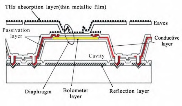
Fig. 14 Schematic diagram of double-layer microbridge structure for terahertz detection
In 2009, the Canadian INO company designed the optical lens required for terahertz imaging based on VOx thermosensitive materials, and carried out imaging experiments. Afterwards, INO Company prepared a 160×120 array anti-reflective coating structure, which realized the transmission imaging of the 5 mm thick polyethylene plastic covering the metal blade. In addition, the company proposed the use of black gold materials, metal thin films, and butterfly antennas to improve the absorption of terahertz radiation.
In 2011, INO Company analyzed the effect of different detection unit sizes on the imaging effect of terahertz detection. With the decrease of the detection unit size, the imaging resolution continues to improve. INO company has developed a micro-bridge structure with a pixel size of 312 μm, and the test found that the micro-bridge structure has obvious deformation.
In 2012, INO proposed the catadioptric terahertz detection imaging lens and micro-scanning image processing method, which improved the terahertz imaging quality.
In 2013, INO Corporation launched a 384×288 array-scale terahertz camera with NEP = 50 pW Hz-1/2 at 1.04 THz, which can perform transmission imaging of blades in envelopes. In 2012, CEA-Leti of France developed a monolithic multispectral detector, which consists of an infrared detector, a light-emitting diode, and an α-Si THz microbolometer, capable of imaging in the visible, infrared, and terahertz bands, and The NEP of the system <10-11W/Hz1/2.
In 2018, Marchese reported the optimized design of the objective lens, the F number of the lens was reduced from 0.95 to 0.60, and the focal length was 44mm, which significantly improved the quality of the terahertz transmission image. It can be seen that the terahertz imaging technology not only significantly improves the imaging quality of the terahertz system by introducing a thermally sensitive microbridge structure, but also makes it have the characteristics of room temperature work, real-time imaging, miniaturization and practicality.
3 Applications of terahertz imaging technology
With the continuous deepening of research on terahertz imaging technology, countries are increasingly aware of the importance of terahertz imaging technology. Especially the United States has made great progress in the field of terahertz imaging technology, and some European countries have also made many important research results in the field of terahertz.
Although our country started late in the field of terahertz research, our country has given great attention and strong support to the development of terahertz technology, which has greatly promoted the rapid development of terahertz technology in our country.
The excellent characteristics of terahertz imaging technology can be applied in the fields of national security, security inspection, biomedicine, non-destructive testing, target radar imaging, environmental monitoring and astronomical research, and has very important practical and academic value.
3.1 Security Check
Terahertz waves have strong penetrability and low radiation characteristics, and are safer than X-rays. They will not cause harmful ionization reactions in biological tissues, and have fewer safety problems for organisms, which greatly complements X-ray detection. and other deficiencies in detection techniques.
Figure 15 shows the application of terahertz imaging technology in security inspection. Figure 15(a) shows the imaging of the terahertz human body security inspection system developed by CETC 38. Figure 15(b) shows the imaging of the terahertz security inspection system developed by Northrop Grumman.
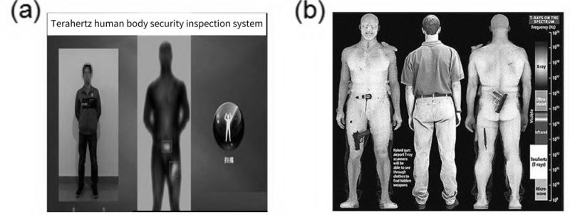
Fig.15 The application of THz imaging technology in security inspection: (a) Imaging for the THz human security detector system developed by China Electric Power 38 Institute; (b) Imaging for the THz security detector developed by Northrop Grumman
3.2 Non-destructive testing
Terahertz waves can penetrate thousands of millimeters thick foam and other materials, detect defects in them, and provide guarantees for the safety of space shuttles and satellites. Figure 16(c) is the terahertz wave image at the metal defect, and (d) is the detection result of the foam board defect. The detection result comes from the Terahertz Research Center of Rensselaer Polytechnic University in the United States.
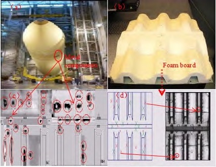
Fig.16 THz image of space shuttle defect
3.3 Biomedicine
Terahertz radiation not only has low ionizing radiation, but also the rotation and vibration energy levels of many biological macromolecules and DNA molecules are mostly in the terahertz band, and biological tissues have a unique response to terahertz waves.
Therefore, terahertz technology can inspect biological tissues to determine whether there are lesions in biological tissues for timely treatment. In addition, terahertz imaging has good spectral resolution characteristics, which can quickly determine injured or diseased tissues. Figure 17 is a terahertz image of tumor tissue.
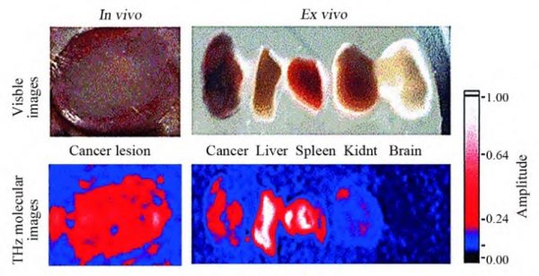
Fig. 17 THz images of tumor tissue in vivo and in vitro
3.4 National Security
Due to the strong penetrating ability of terahertz waves, experiments have proved that terahertz radiation can penetrate non-metallic walls such as wood and soil to obtain indoor images. Using terahertz imaging technology to grasp the indoor situation from outside the wall plays an important role in ensuring the safety of anti-terrorism personnel and the execution of anti-terrorism tasks.
3.5 Environmental monitoring and astronomical research
Terahertz imaging technology can not only detect carbon monoxide (CO), water (H2O), nitrogen (N2), oxygen (O2) and other gases in the atmosphere, but also the electromagnetic waves emitted by most substances in the universe are in the terahertz band. Hertzian imaging can detect and image the cold and dark regions in the universe, such as studying the formation of black holes and observing distant celestial bodies, see Figure 18.
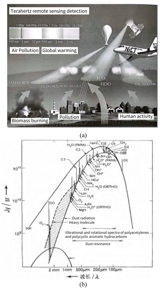
Fig.18 The application in environment and astronomy field: of terahertz imaging technology: in environmental monitoring (a) and astronomical research (b)
4 Limiting factors of terahertz imaging technology
Although terahertz imaging technology has great advantages in many aspects, it also has certain limitations, which are mainly reflected in the following aspects:
- Due to the strong absorption of water molecules on terahertz waves, objects with high water content cannot be clearly imaged, which limits the application of terahertz technology in the detection of medical biological tissues.
The moisture contained in the air will also greatly affect the detection distance of terahertz technology. - Terahertz detectors are sensitive to temperature, and changes in the external temperature will affect the detection results. Therefore, try to keep the temperature constant when performing imaging experiments.
- Due to the time-consuming problem in the terahertz imaging process, too long time will have a certain impact on the imaging quality of the sample. Imaging time can be shortened by using large-area electro-optic crystals (eg, LiNbO3, GaSe, ZnTe) combined with CCD, CMOS cameras.
- When using a reflective terahertz imaging system, it should be ensured that the terahertz signal is incident on the surface of the sample, otherwise the terahertz wave reflected by the lens will interfere with the terahertz wave reflected by the sample, which will affect the imaging results.
- Terahertz signals have problems of low output power and narrow bandwidth in terms of output power and bandwidth. In addition, issues such as stability, high efficiency, and environmental protection should also be considered when studying terahertz sources.
- When suspicious objects are covered by metal, terahertz imaging technology cannot play a role. At this time, it can be combined with other detection technologies, such as metal detectors.
- The terahertz imaging system with a microbridge structure at room temperature cannot perform passive imaging, so an external terahertz radiation source needs to be combined with the imaging; in addition, the system has better detection performance in the high-frequency terahertz band, but the response in the low-frequency band is biased. Low.
Since my country’s terahertz imaging technology started late and is not yet mature in terms of key technologies, it needs to be further improved and perfected in terahertz radiation, terahertz transmission, terahertz modulation, and terahertz detection.
5 Summary and Outlook
This paper summarizes the main research progress of terahertz imaging technology, and introduces the typical applications of terahertz imaging technology. The terahertz imaging system must meet the performance requirements of high resolution, good real-time performance, portability and high sensitivity.
For the current technical means that can effectively improve the performance of terahertz imaging, we believe that the following points can be considered:
- Continuously develop new devices by using high-performance materials (such as graphene, silicene, black phosphorus, etc.) and utilizing the excellent performance of new materials.
- Increase the coupled absorption of terahertz radiation by using metasurface structures.
- By eliminating background noise and interference effects, the ability of the terahertz imaging system to obtain information can be improved. For example, technologies such as single-pixel imaging, CS theory, and optimized optical systems can be developed.
- By introducing a terahertz antenna, the THz energy is coupled to the detection unit of the detector to improve the ability to collect terahertz radiation.
- Compared with traditional terahertz imaging devices, terahertz focal plane detection array devices with microbridge structure have the advantages of wide detection band, large array scale, high integration, real-time imaging, miniaturization, portability and practicality.
Our country’s terahertz imaging technology started relatively late, and many key technologies still need to be overcome. Therefore, scientific research institutions and industrial groups need to strengthen cooperation to develop terahertz imaging technology with independent property rights, so that terahertz imaging technology can be industrialized in my country. Better serve my country’s national defense and people’s livelihood.