Example of Scratch-Digs Defects
Surface defects on optical elements (scratches and digs) are designated by two numbers. The first number refers to scratch width, and the second number refers to dig diameter. For example, 80-50 means that the maximum allowable width of a scratch is 80 and the maximum allowable dig diameter is 50 by comparing both numbers to the quality standards, per drawing no. C7641866.
Note that the combined length of the maximum-size scratches located on each surface of a circular element should not exceed one-fourth of the surface diameter. Further notes:
- To calculate surfaces other than circular ones, the computing diameter should be that of a circle of equal area.
- Scratches beyond the free aperture (i.e., clear aperture, or CA) of any surface of any element should not be considered when calculating the equal value of the existing scratches.
- The surface quality outside the free aperture of any element should be considered 80-50 unless otherwise required.
- Coating scratches should be considered separately from the substrate scratch requirements, and the substrate scratches should have the same size unless otherwise required.
- Here we will illustrate some examples of scratch and digs defects.
Scratch example 1
The scratch-dig requirement for a 60-mm-diameter surface is 80-50. and two scratches are found with the maximum size (80). One is 10 mm long, and the other is 12 mm. The combined length of the two scratches is 22 mm, and a quarter of the surface diameter is 15 mm. The combined length is larger than the qurater-diameter (22 >15), so the findings do not conform to the requirement, and the item is rejected.
Scratch example 2
The scratch-dig requirement for a 120-mm-diameter surface is 80-50, and two scratches are found with the maximum size (80). One is 12 mm long, and the other is 17 mm. The combined length of the two scratches is 29 mm, and a quarter of the surface diameter is 30 mm. The combined length is smaller than the quarter-diameter (29 < 30), so the findings conform to the requirement, and the item is accepted.
The maximum size of a scratch (along with various-size scratches located on each surface of the circular tested element, the sum of the scratch number sizes) times the ratio of their length to the relevant diameter of the surface or appropriate zone (i.e., the requirement for the scratch-dig grade stated in the relevant drawing is needed for only a partial area of a given surface; see paragraph 3.5.2.1.1 of MIL-PRF-13830B) should not exceed half of the maximum scratch number.
Scratch example 3
The scratch-dig requirement for a 120-mm-diameter surface is 80-50, and the following scratches were found: one scratch 12 mm long and size no. 40, one scratch 20 mm long of size no. 60, and one scratch 25 mm long of size no. 80.
The following calculation is made:

Scratch size no. 31 is smaller than half of the maximum size (80/2) the findings conform to the requirement, and the item is accepted.
Scratch example 4
The scratch-dig requirement for a 100-mm-diameter surface is 80-50, and the following scratches were found: one scratch 14 mm long and size no. 40, two scratches 20 mm long and size no. 60, and one scratch 20 mm long and size no. 80. The following calculation is made:

Scratch size no. 46 is larger than half of the maximum size (80/2 ¼ 40), so the findings do not conform to the requirement, and the item is rejected.
When there is no maximum-size scratch, the sum of the products of the scratch numbers times the ratio of their length to the diameter of the element or appropriate zone should not exceed the maximum scratch number.
Scratch example 5
The scratch-dig requirement for a 60-mm-diameter surface is 60-40, and the following scratches were found: two scratch 12 mm long and size no. 40, four scratches 20 mm long and size no. 40, and two scratches 25 mm long and size no. 20. The following calculation is made:
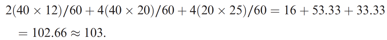
Scratch size no. 103 is larger than the maximum size scratch number (60), so the findings do not conform to the requirement, and the item is rejected.
Regarding digs
- The dig number is the actual diameter of allowed regular defects specified in units of 1/100 mm. In the case of an irregularly shaped dig, the diameter should be the average of the maximum length and the maximum width.
- The permissible number of maximum-size digs should be one per each 20 mm of diameter on any single optical surface. The sum of the diameters of all digs, as estimated by the inspector, should not exceed twice the diameter of the maximum size specified per 20-mm diameter.
- Digs less than 2.5 microns should be ignored.
- All digs on each surface whose dig quality is no. 10 or smaller should be separated edge to edge by at least 1 mm.
- Coating defects, as in scratches, should be considered separately from the substrate digs requirements, and the substrate ones should have the same size unless otherwise required.
Dig example 1
The required maximum permissible size dig on a lens’ surfaces is 50 (0.5 mm).
The diameter of the free aperture of the surface is 40 mm. An irregularly shaped defect is found on one surface; the length of the defect is 0.7 mm, and the width is 0.2 mm. The following calculation is made:

which is smaller than the maximum permitted dig (50), so the defect is accepted.
Dig example 2
The required maximum permissible size dig on a lens’ surfaces is 40 (0.4 mm).
The diameter of the free aperture of the surface is 40 mm. On one surface, the following defects (digs) are found: one irregularly shaped defect with a length of 0.5 mm and a width of 0.3 mm, two regularly shaped defects of 0.3 mm, and two regularly shaped defects of 0.2 mm. All defects were found to be within a diameter of 20 mm. The following calculation is made:

which is larger than the maximum permitted dig (40), so the element is rejected.