Optical Height Measurement System Based on Binocular Camera
According to the binocular stereo vision model, this paper builds a laboratory-specific height measurement system. By using the Matlab toolbox to calibrate the binocular camera to obtain many parameters required by the experiment, the paper establishes the relationship equation between the corrected world coordinates and the pixel coordinates through image correction technology. Under the programming environment of VS2015 combined with OpenCV, the stereo matching algorithm and the parallax theory are used to obtain the three-dimensional spatial information of the target surface. Finally, the space coordinates of the same target are obtained by selecting two characteristic points to achieve the purpose of height measurement. The experimental results show that the system can achieve 3D information measurement of real scenes well.
Key words
binocular stereo vision; camera calibration; disparity map; height measurement
Introduction
Since ancient times, human beings have been trying to use tools to describe everything they see. With the continuous development of modern technology, new height measurement technologies are constantly being proposed. For colleges and universities, obtaining the size of surrounding objects more accurately and quickly in the laboratory is helpful to verify the experimental results in stages. Compared with ordinary measurement methods that are time-consuming, laborious and inefficient, binocular vision height measurement technology has Multi-target simultaneous detection, non-contact, high-precision, high-efficiency advantages.
In the field of binocular vision measurement, many scholars at home and abroad have done a lot of research and practice. In 1966, the least squares method was first used by Hallert in the processing of calibrating observation data, and the application in the field stereo coordinate measuring instrument achieved breakthrough and accurate results. Zhou Kejie et al. introduced a 3D measurement system using a binocular camera combined with encoded structured light. The system can obtain a 3D point cloud matrix by moving the measuring instrument, and then complete the measurement of large curved surfaces. Although the current theoretical research on stereo vision technology has gradually improved, the requirements in different scenarios are also different, which puts forward higher requirements for the robustness and stability of the entire stereo vision system.
In order to improve the accuracy of the obtained camera-related parameters, the calibration method of binocular vision is mainly improved, and the method of pre-calibration + single-target + dual-target calibration is pioneered for stereo calibration, and the experimental results are finally demonstrated. This method works.
1. The principle of binocular height measurement
As an important branch of machine vision, binocular vision measurement technology uses a pair of binocular modules to simulate the visual mechanism of the human eye, so as to obtain two images of the same scene from two different perspectives, and then establish a corresponding mathematical model based on the principle of parallax. To restore the depth information in the scene, and finally use the similarity principle to calculate the spatial three-dimensional coordinates of the highest and lowest points on the same surface of the target object.
The binocular stereo vision model is shown in Figure 1. In Figure 1, PL and PR are the projections of the point P (x, y, z) on the imaging planes of the left and right cameras respectively, OR and OL are the optical centers of the left and right cameras, n is the principal optical axis vector of the camera, and ƒ is the focal length of the camera. . If the projection coordinates PL and PR of the spatial point P on the left and right image planes and the camera calibration parameters are known, the three-dimensional spatial coordinates of the point P can be calculated.
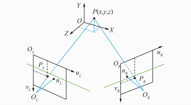
Fig.1 Binocular stereo vision model
1.1 Dual goal setting
Binocular camera calibration requires the determination of the position of each feature point on the reference object relative to the world coordinate system (XW, YW, ZW), and the corresponding relationship between the image plane coordinates and the three-dimensional space coordinates. This mapping relationship is mainly determined by the binocular camera. , the external parameters are determined. In other words, the main purpose of binocular camera calibration is to obtain the internal and external parameters of the camera and the corresponding distortion coefficients, because this will directly affect the results of binocular measurement.
The calibration method adopts the single-plane checkerboard method proposed by Professor Zhang Zhengyou, hereinafter referred to as Zhang’s calibration method, and the calibration board is shown in Figure 2. Zhang’s calibration method directly fuses the world coordinate system with the calibration plate plane, that is, ZW = 0, the homogeneous coordinates of any point P on the calibration plate plane are (XW, YW, 0, 1), which is expressed in the image pixel coordinate system as (u, ν, 1 ), image physical coordinate system (x, y, 1 ), camera coordinate system (XC, YC, ZC), expressed in matrix form as:
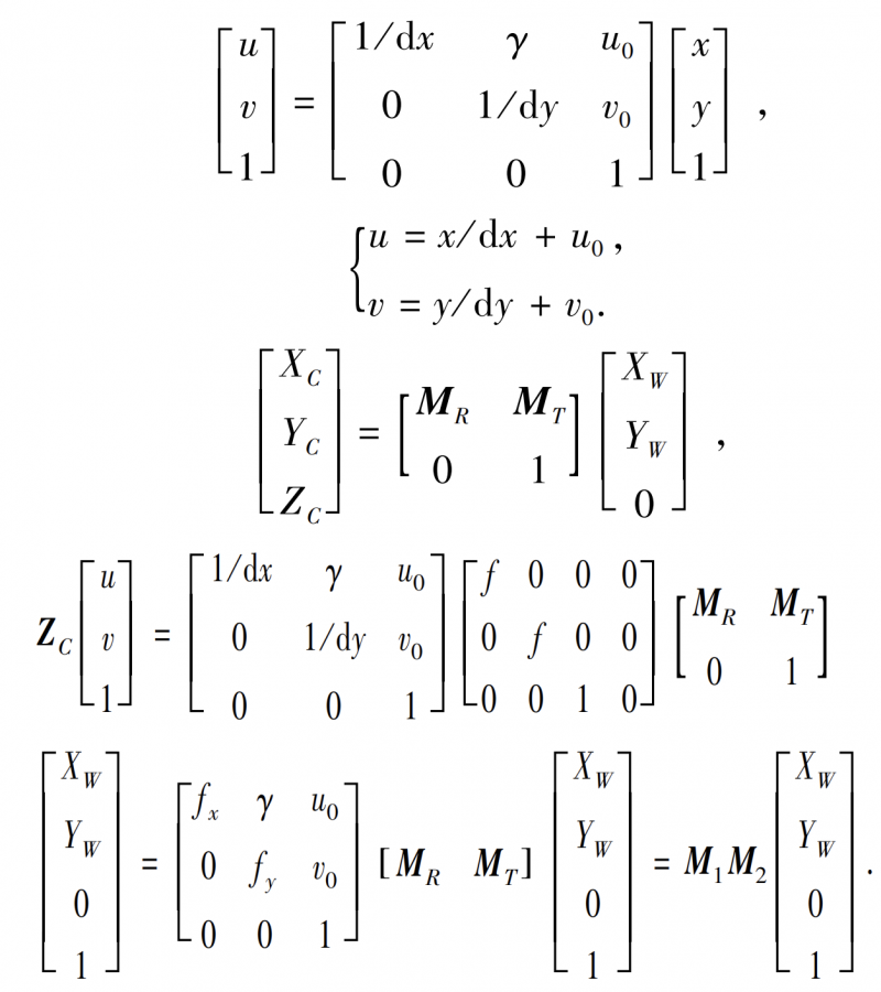
Among them, M1 represents the built-in parameter matrix of the camera, which is determined by fx, fy, u0, ν0, and γ, but γ is generally regarded as 0 and used. These five parameters are only related to the internal structure of the camera, and M2 contains the rotation matrix MR and translation matrix MT. .
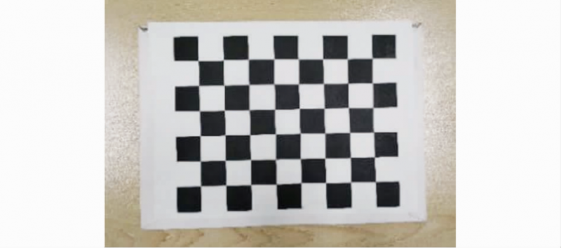
Fig. 2 Calibration board
Since many parameters are obtained in the calibration stage, in order to make the calibration result more accurate, the method of pre-calibration + single-target calibration + dual-target calibration is creatively used.
The pre-calibration is shown in Figure 3. In the pre-calibration stage, Matlab’s automatic calibration toolbox-Stereo Camera Calibrator was used to screen and calibrate the collected 24 sets of checkerboard images, and then the image pairs with large errors in the calibration process were eliminated according to the Mean Error Pixels index.
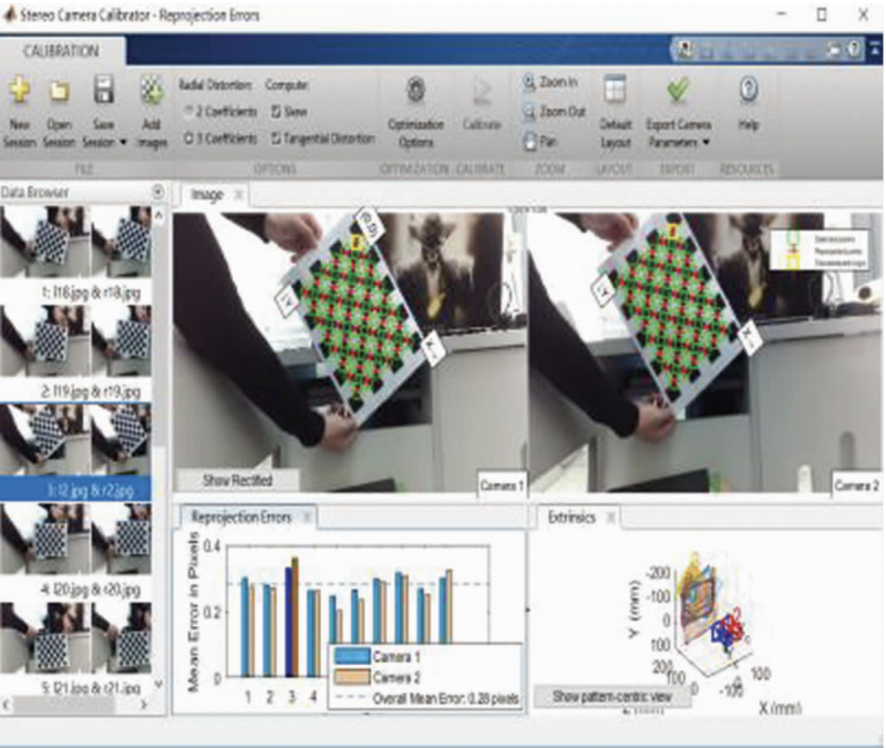
Fig. 3 Pre-calibration
The single target setting is shown in Figure 4. The corner selection is shown in Figure 4(a). In the second stage, use the calib toolbox to manually calibrate the filtered left and right views respectively. This process mainly includes manually setting the corner points and automatically extracting the corner points, thereby obtaining two sets of parameters for single-object calibration, see Table 1.
Table 1 Build-in parameters of left and right camera
| wdt_ID | Attributes | Left Camera | Right Camera |
|---|---|---|---|
| 1 | Focal Length | [1 230.788 42 1 244.18806] ± [2.853 18 2.978 42] | [1 247.161 89 1 234.775 46] ± [2.395 85 2.711 14] |
| 2 | Main Point | [608.242 70 257.838 62] ± [4.342 02 4.447 98] | [589.279 35 272.085 24] ± [4.626 46 4.436 35] |
| 3 | Distortion Coefficient | [0.253 87 -0.506 67 -0.052 99 -0.012 18 0.000 00] ± [0.075 60 0.582 88 0.009 54 0.003 38 0.000 00] | [0.239 34 -0.186 53 -0.059 75 -0.021 71 0.000 00]± [0.071 40 0.285 46 0.010 34 0.004 28 0.000 00] |
Figure 4(b) shows the relative three-dimensional space diagram between the monocular lens and the calibration board.
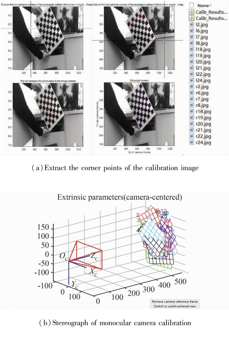
Fig. 4 Monocular calibration
Next, in the third stage, the Stereo Calibration toolbox is used to integrate the results of the single-objective targeting by importing the results of the second stage. The three-dimensional space map of the two-target fixed is shown in Figure 5. The spatial configuration and calibration plane of the two cameras are displayed in the form of a 3D map. After the global stereo optimization, the parameter matrices Mr1 and Ml1 of the left and right cameras, as well as the rotation matrix MR and the translation matrix MT are finally obtained. The calculated results obtained by the study are:
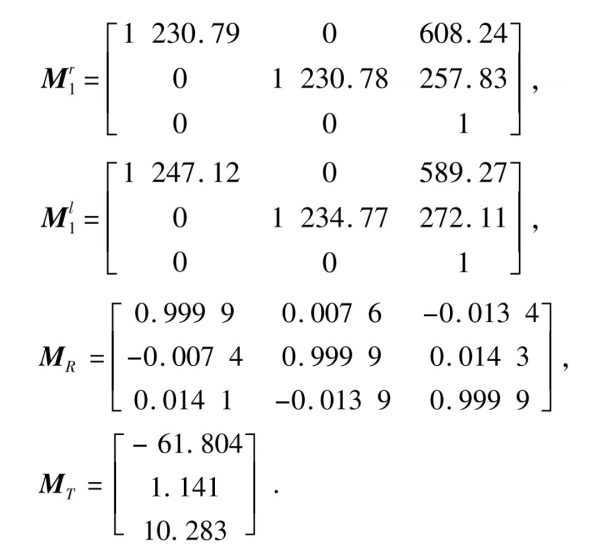
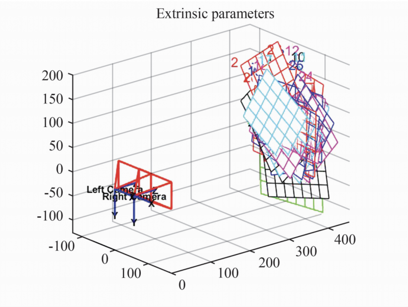
Fig. 5 Three-dimensional space map of binocular calibration
1.2 Stereo correction
In order to estimate the depth information of a point through two images, it is necessary to strictly ensure that the point can be matched in the two images. At the same time, in order to improve the matching efficiency, the imaging planes of the left and right cameras should be on the same plane. However, in practice, it is not possible to keep the optical centers OR and OL on the same axis only by laying the camera flat, see Figure 1. At this time, it is necessary to use the image stereo correction technology to re-project two different image planes onto the same plane, so that the two images meet the matching conditions.
The corrected binocular stereo vision model is shown in Figure 6. It can be seen from Figure 6 that after stereo correction, the image distortion is eliminated, the X-axis of the two cameras are coincident, the optical centers OR and OL of the left and right cameras are the baseline B, the optical axis is perpendicular to the camera imaging plane, and the left and right imaging planes are Each row is strictly horizontally aligned, satisfying the epipolar constraints, and the search range of matching points is also reduced from two-dimensional to one-dimensional. Under this structure, it is very convenient to find the matching relationship between the projections uL and uR of point P on the left and right imaging planes.
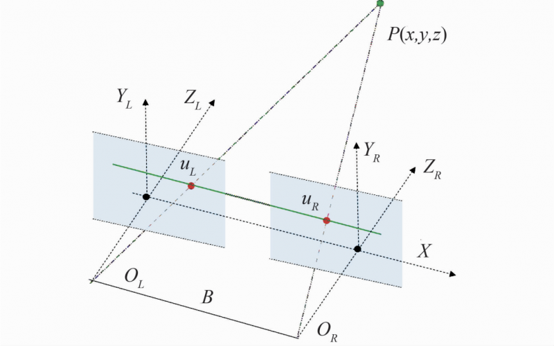
Fig. 6 Binocular stereo vision model after stereo correction
1.3 Stereo matching
Stereo matching is the core process of binocular stereo measurement. According to the input reference image R and target image T, the disparity map corresponding to the reference image R can be obtained, and then the three-dimensional space information of the target can be more accurately calculated, which is the process of binocular matching.
After the stereo correction, the imaging planes of the left and right cameras are coincident, so for the convenience of explanation, Fig 6. The left and right image pairs after stereo correction are shown in Figure 7.
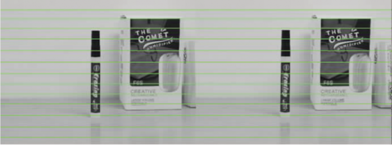
Fig.7 Left and right image pairs after stereo correction
The principle of triangulation is shown in Fig 8. It can be seen from Figure 8 that under the condition that the optical axis is parallel to the focal length f of the camera lens, B is the baseline length, the Y axis is perpendicular to the screen and points inward, and the target point P (x, y, z) is imaged on the left and right camera imaging planes.
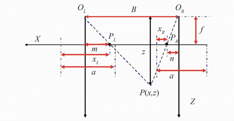
Fig. 8 Triangulation principle
The coordinates are PL and PR respectively, α is the width of the camera lens, the distance from the center of the left and right lenses to PL, PR is m, n, according to the principle of triangulation, it can be deduced:
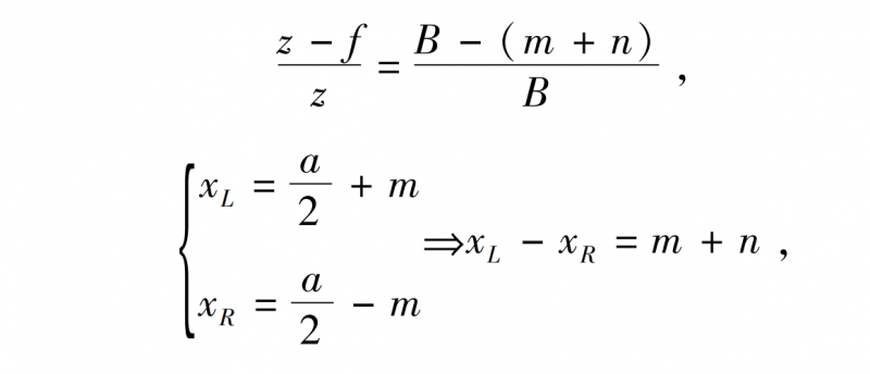
From the above formula, we can get:
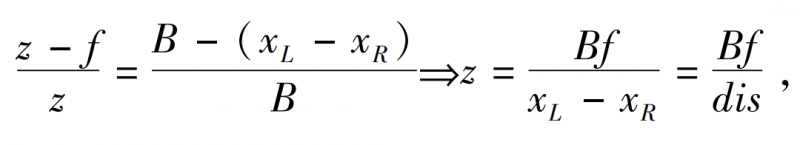
The same can be obtained:

The obtained (x, y, z) at this time is the coordinates of the target in the world coordinate system (XW, YW, ZW), where the left and right camera focal length ƒ and baseline length B are constants obtained before matching, and the parallax dis, that is, the correspondence between the left and right camera pixels, is the core element to obtain the depth z.
2. Experiment and result analysis
2.1 Construction of experimental platform
One of the characteristics of the binocular stereo vision system used in the laboratory is low cost and simple operation. Its core components are a binocular vision module, a special bracket and a computer. Use a USB data cable to connect the computer and the binocular camera. The physical map of the binocular vision module is shown in Figure 9, and the main parameters are shown in Table 2.
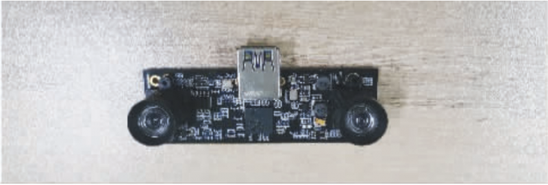
Fig.9 Binocular camera physical map
Table 2 Binocular camera parameters
| wdt_ID | Parameter Type | Specific configuration |
|---|---|---|
| 1 | Interface | USB3.0 (compatible USB2.0) |
| 2 | Transfer speed/(MB·S^-1) | ≥ 100 |
| 3 | Resolution | 1280×480 |
| 4 | Frame rate/fps | 30 |
| 5 | Interface Protocol | UVC protocol |
| 6 | Size/(mm*mm) | 74×23 |
The construction of the platform is also very fast, just fix the binocular camera on the bracket, then fix the bracket on the laboratory table, and finally use the USB data cable to connect with the notebook to complete. The software platform of the entire binocular ranging system is based on the Win10 desktop operating system, the calibration box tool of Matlab2010b is used for camera calibration, and the operating environment of the stereo matching algorithm is Microsoft Visual Studio 2013. The specific operation process of the whole system is shown in Figure 10.
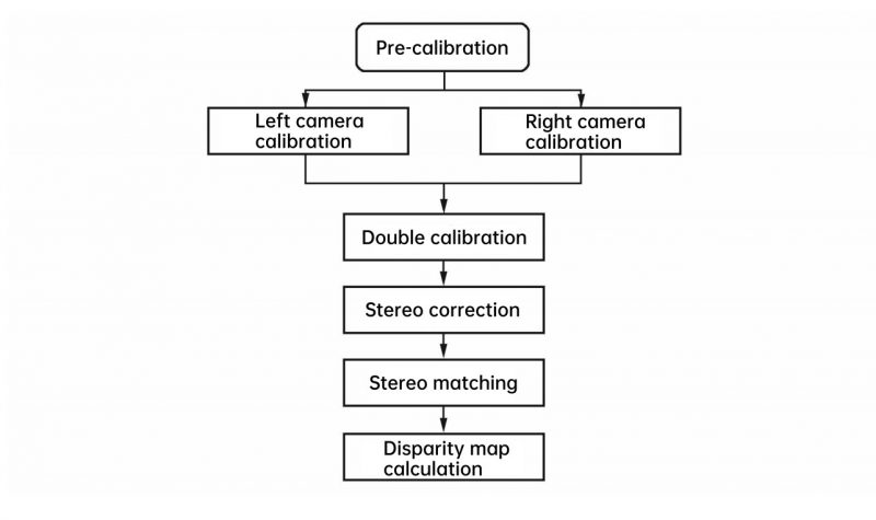
Fig. 10 Binocular stereo vision ranging process
2.2 Experimental results
The SGBM algorithm in the semi-global matching algorithm is used to compare with the BM (Block Matching) algorithm in the local stereo matching algorithm. Figure 11 shows the output disparity map after performing stereo matching on Figure 7 using the BM algorithm. It can be seen from the disparity map that the general outline of the entire scene is basically restored, but due to the large number of incorrect matching points, the information loss is very serious, and the overall recognition of the disparity map is relatively poor, so it has no reference value
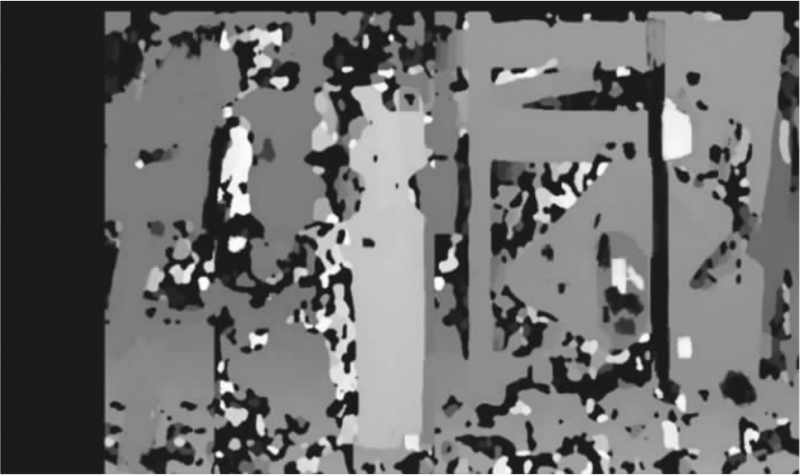
Fig. 11 BM algorithm output disparity map
Figure 12 shows the output disparity map after stereo matching of Figure 7 using the SGBM algorithm. Although the information is also missing, the overall contour is more complete, the resolution is higher, and there are fewer incorrect matching points than the results of the BM algorithm.
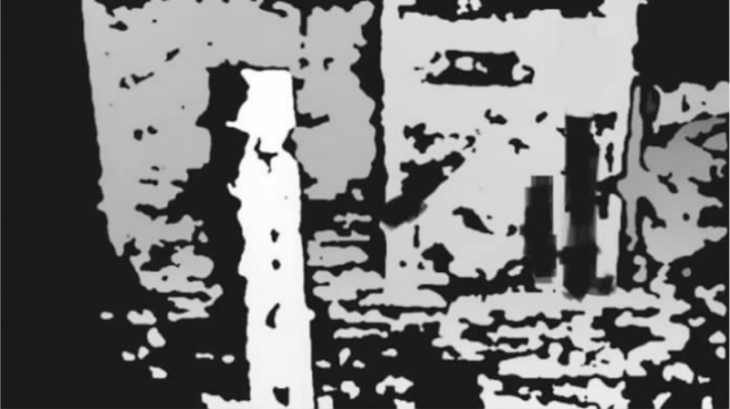
Fig. 12 SGBM algorithm output disparity map
Due to the limited experimental conditions, only two matching algorithms are used temporarily. The error results are shown in Table 3. The measurement results of this system are relatively accurate, and the error is controlled at about 1%.
Table 3 Experimental data and error analysis
| wdt_ID | System measurement height a /mm | Actual height b /mm | Deviation ((b-a) / a) /% |
|---|---|---|---|
| 1 | 134.892 | 136.4 | 1.105 |
| 2 | 229.524 | 231.8 | 0.009 |
| 3 | 486.829 | 491.3 | 1.009 |
3. Conclusion
Matlab is used to develop the acquisition of real scene image pairs and the calibration of the binocular camera used in the experiment, and a variety of calibration methods are combined in the stage of binocular calibration, thus ensuring the accuracy of the built-in and external parameters of the obtained camera. Combined with OpenCV in the VS2013 programming environment, the correction of the binocular image is completed, and the disparity maps generated by the BM and SGBM algorithms are compared in the binocular matching stage. The final experimental results show that the system can well realize the 3D height measurement of real scenes.