A Detailed Summary of Nd:YAG Laser Crystal
1. Nd:YAG Laser Crystal
The Nd:YAG laser is by far the most commonly used type of commercial solid-state laser. Neodymium-doped yttrium aluminium garnet Y³-x NdxAl5O12 (Nd:YAG)possesses a combination of properties uniquely favourable for laser operation. Undoped pure Y³Al5O12 is a colourless, optically isotropic crystal which possesses a cubic structure characteristic of garnets. Its optical properties are isotropic; the refractive index does not depend on the direction of the light nor its polarization. The cubic structure of YAG favours a narrow fluorescence linewidth, which results in a high gain and a low threshold for laser operation. The YAG host is hard, is of good optical quality and has a high thermal conductivity. The basic physical and chemical properties of YAG crystals are summarized in Table 01.
The major laser activator ion for YAG is Nd3+, which replaces isomorphic Y3+ ions. As the Nd3+ ion radius (0.98A)exceeds that of the Y3+ion (0.90A), the entry of neodymium ions into the YAG lattice is limited, up to a concentration of a few per cent. In Nd:YAG, trivalent neodymium substitutes for trivalent yttrium, so charge compensation is not necessary.
It is possible to grow a transparent Nd3+:YAG crystal with an atomic concentration of Nd3+ of up to 1.5% with the substitution of Y3+ ions. The Nd doping level in YAG is sometimes expressed in different concentration units: a concentration of 1.0% Nd atoms in the lattice is equivalent to 0.727% Nd or 0.848 wt% Nd2O3, respectively. The concentration of Nd³+ sites in these cases is 1.386×1020cm-3.The growth is carried out by the Czochralski (CZ) method (pulling from a melt) using iridium crucibles. The high-quality crystal must be grown with a very slow growth rate (0.5mm h-1).
The difference in the ion radii of Nd3+ and Y3+ determines the distribution coefficient of neodymium ions in the melt-crystal system. The concentration of Nd ions in the growing crystal is much less than the concentration in the melt, because the distribution coefficient is only ~0.18.
Table 01 Comparison of Nd:YAG, Nd:YLF and Nd:YAlO3
Because the Nd distribution coefficient is low, not all Nd:YAG crystal boules are uniformly doped. This problem arises as a result of the crystal growth mechanism. In substituting the larger Nd3+ for a Y3+ in Y3Al5O12, the Nd3+ is preferentially retained in the melt. The increase in the concentration of Nd from the seed to the terminus of a 20-cm long boule is about 20%-25%. For a laser rod 3-8cm long, this end-to-end variation may be 0.05-0.10wt% of Nd203.
In addition to CZ growth from iridium crucibles, crystals can also be grown by zone melting in molybdenum containers.However,the highest quality crystals are produced by CZ growth. In this method, the melt is induction heated via the iridium crucible, which contains the starting materials. The growth process originates on the seed rod. Since the temperature of the seed crystal is lower than the temperature of the melt, the melt gradually crystallizes on the seed crystal during the slow lift and rotation rates(10-20 rev min-1). The crystal orientation of the growing boule reproduces that of the seed crystal. For the crystal growth process, the melt temperature must be maintained above the melt temperature of YAG (1970°C) with a very high degree of accuracy. At such high melt temper-atures, one difficulty is the crucible material. For Nd:YAG, the best material is iridium, although its high cost and rarity pose serious problems in the manufacture of Nd:YAG crystals. The CZ growth of Nd:YAG is a capital-intensive process. A single iridium crucible for growing large-sized crystals costs almost US $100,000. Even worse, a significant portion of the crucible is unrecoverable, as it is ‘burned-up’ during use, limiting its lifetime. The capital investment is increased by the additional need for protection systems to ensure a continuous supply of electrical power, cooling water and other utilities essential for maintaining a reasonable productivity level. Therefore, the Nd:YAG rod, particularly a slab-shaped crystal, is often one of the most expensive components in the laser system.
YAG crystals grow in an inert atmosphere of nitrogen or argon. At the optimum growth rate of 0.5mm h-1, the manufacture of the average size Nd:YAG crystal boules (a length of about 150mm with a diameter of about 100mm) takes about 300h, i.e. about 2 weeks. The CZ growth enables production of large Nd:YAG crystals. The biggest Nd:YAG crystal grown to date is 100mm in diameter and 300mm long.
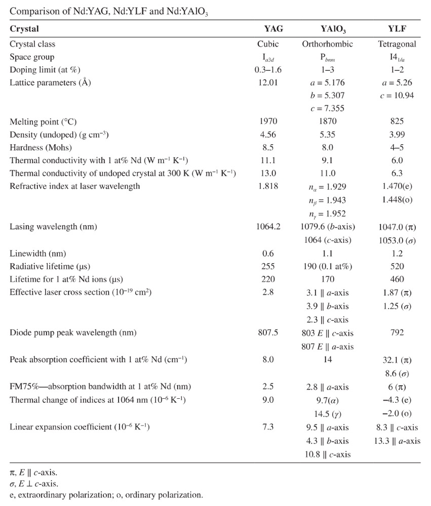
During growth, defects form in the central part of the crystal, giving rise to mechanical and optical distortions. Electron microprobe studies have revealed that, in the core region, the Nd concentration can be as much as twice as high as in the surrounding areas. The core originates from the presence of facets on the growth interface, which have a different Nd3+ distribution coefficient from the surrounding growth surface. These compositional differences cause corresponding differences in the thermal expansion coefficients, which, in turn, give rise to the stress patterns observed as the crystals cool down from the growth temperature. Annealing does not seem to eliminate the core and, thus far, no way has been found to prevent the formation of facets on the growth interface. Therefore, active elements are cut out from the peripheral parts of Nd:YAG crystals. As a rule, the active elements are made in the form of long thin cylinders with their axis directed along the growth of the crystal boule. By changing the orientation of the seed rod, it is possible to change the orientation of the crystallographic axes in an active element. Cylindrical elements produced from Nd:YAG have, as a rule, diameters of 3, 4, 5, 6.3, 8 or 10mm and lengths of 32, 40, 50, 65, 80, 100, 125, 150 or 200mm.
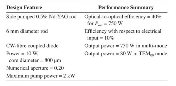
In specifying Nd:YAG rods, the emphasis is on size, dimen-sional tolerance, doping level and passive optical tests of rod quality. Cylindrical rods with flat ends are typically finished to the following specifications: ends flat to λ/10, ends parallel to ±4 arcsec, perpendicularity to rod axis to ±5min and rod axis parallel to within ±5° to the [111] direction. Dimensional tolerances typically are ±0.5mm in length and ±0.025mm in diameter. Most suppliers furnish laser crystals with a photo-graph showing the fringe pattern of the crystal as examined by a Twyman-Green interferometer. A double-pass Twyman-Green interferometer quickly reveals any strained areas, small defects or processing errors. The optical quality of such rods is normally quite good and comparable to the best quality of optical glass. For example, 6mm by 100mm rods cut from the outer sections of 20mm by 150mm boules typically may show only one to two fringes in a Twyman-Green interferometer. Usually,lamp-pumped Nd:YAG lasers with an average out-put power of up to 500 W use a single rod up to 10mm in diameter and 150mm long. Higher-power systems with outputs of 2-3kW can have up to four or, less-commonly, six pump heads with a laser rod up to 200mm long.Later rectangular slab configuration crystals with up to 10mm by 25mm cross-sectional dimensions and lengths in excess of 200mm have entered the market (Figure 01).
The spectroscopic properties of Nd:YAG are determined by the basic properties of an Nd3+ ion, as slightly modified by the YAG crystalline matrix. Neodymium is a rare-earth metal. The optical and laser properties of trivalent neodymium, as well as other rare-earth ions, are determined by the transitions inside the 4f-electronic shell (Figure 02).
FIGURE 01 Nd:YAG boule cross section showing the facet regions and location of slab and rod sites.
Under the action of the electrostatic crystal field of the lattice, the energy levels split into Stark levels, which vary from crystal to crystal, and while the lines broaden as a result of interactions with the phonons of the crystal lattice. At room temperature, the main 1.06 um line in Nd:YAG is homogeneously broadened by ther-mally activated lattice vibrations.
The structure of the energy-level-free Nd3+ion is determined by the electrons’ Coulomb interactions with the nucleus and with each other, and also with the spin and orbital moments of the electrons. The lowest Nd3+ion energy level belongs to a 4IJ, atomic state. This means that three electrons of the Nd3+ion, being on the 4f shell, have a total spin moment S of 3/2 and an orbital moment L of 6. As a result of the spin-orbital interaction, the 4f multiplet is split into four Stark levels with total moment J from L-S=6-3/2=9/2 up to L+S=6+3/2=15/2.
In Figure 02, the splitting of the lowest 4I levels of Nd3+ with various spin-orbits and Stark splits by the crystal field in a YAG crystal is shown. The energy levels of a free Nd3+ ion are also shown.
FIGURE 02 Energy-level diagram of the free ion and the splitting of the Nd³+ ion inside the crystal field of YAG.
1.1 Energy Levels of Nd³⁺ lons in a YAG Crystal
A detailed diagram of the Nd³+ energy levels in YAG is given in Ref. [1]. All levels of the free ion in crystals split as a conse-quence of the Stark effect arising from the crystal field. Each term is split into (2J+1)/2 components, in particular: 4I9/2 into 5, 4I11/2 into 6, 4I13/2 into 7 and 4I15/2 into 8. Energy splitting between components lies in the ranges of about 10-100cm^-1. In Figure 02, the energy-level diagram for the Nd³+ ion in a YAG crystal is shown at a temperature T of 300 K; however, the Stark splitting is only shown for levels that directly participate in laser generation. The number of levels from the Stark splitting is large, compared to those for the free ion. However, the weak splitting of the levels is grouped around the free ion energy. As a result of the low symmetry of the local crystal field of the Nd³+ ion YAG, the degeneracy of levels in YAG is removed completely, except for Kramer’s degeneracy of the Jz projection, which can be removed only by using an external magnetic field.
According to parity selection rules, optical transitions are forbidden between the energy levels in one electronic shell. In our case, this means that either the probability of all optical transitions between levels is small or the time for spontaneous optical transitions between levels is large (in comparison with the time constant of permitted optical transitions, being of the order of 10^-8-10^-9s).For Nd³+ ions,all transitions between levels of the 4f shell are weak. Their intensity differs from zero as a consequence of mixing the 4f shell with a shell with opposite parity (for example, the 5d shell) under the action of odd harmonics arising from the crystal field. The intensity of transitions strongly varies from crystal to crystal and is defined by the specific properties of the matrix.
1.2 The Lifetime of Nd³⁺ lons in YAG
In the general case, the lifetime of the energy levels is determined, as noted earlier, by radiative and non-radiative relaxation between levels, which has been investigated by many research groups. We shall consider them more in detail.
According to the energy levels of Nd³⁺ ions in garnet crystals, optical transitions can occur from the metastable levels, including the ⁴F₃/₂ level, downwards, to the ⁴I₉/₂-⁴I₁₅/₂ multiplets. All these transitions are forbidden and their characteristic lifetimes are about 10⁻³-10⁻⁴s. The energy distances between the pump levels above the ⁴F₃/₂ level are rather small in comparison with the YAG phonon energy. Therefore, the probabilities for non-radiative transitions between them are great and the lifetimes are accordingly small (≤10⁻⁶s). Thus, the Nd³⁺ ions, upon being excited to pump levels, relax to the ⁴F₃/₂ level quickly, in practice completely non-radiatively.
The ⁴F₃/₂ level is metastable because the next lower level is separated from it by 4698cm⁻¹. Therefore, non-radiative transitions downwards from the ⁴F₃/₂ level have a small probability. They can be made only through multi-phonon relaxation requiring close to six phonons; the probability of such transitions is small and the lifetime is great, about 1-3×10⁻²s. As the radiative time for the ⁴F₃/₂, level transition is also great (about 2.5×10⁻⁴s), this level is, therefore, metastable—a long-lived level which is convenient for use as the upper level in a four-level scheme for lasers.
It is worthwhile noting that the ratio-
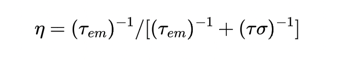
determining the quantum yield of emission from the upper laser ⁴F₃/₂ level in YAG is greater than 99.5% with a fluorescence lifetime of 230 us.
For the lower ⁴I₉/₂-⁴I₁₅/₂ multiplets, the energy distances within and between them are less or comparable to the maximum phonon energy (850cm⁻¹). The transitions within and between these multiplets experience non-radiative relaxations with a short time constant of about 10⁻⁸s.
Thus, in view of the energy distances and lifetimes for Nd³⁺ions in YAG, the laser scheme (see Figure 02) will be close to the ideal four-level system. The pump level ‘4’ includes all levels lying above the ⁴F₃/₂ a level. The metastable transition level ‘3’ is served by the ⁴F₃/₂ state, split into two Stark levels: R₁ at 11 423cm⁻¹ and R₂ at 11 507cm⁻¹. The ‘2’ transitions can be served by any levels of the ⁴I₁₁/₂-⁴I₁₅/₂ multiplets. Moreover, at last, the lowest level is comprised from a set of Stark levels from the ⁴I₉/₂ multiplet. Hence, laser generation on the four-level scheme can occur over the whole range of channels formed by the different Stark levels in the multiplets.
1.3 Effective Emission Cross Sections of Laser Transitions
The emission cross sections of the basic laser transitions of Nd:YAG are well investigated and are described in Ref.[1].In Table 02 the basic lines for Nd:YAG laser generation, the emission cross sections of transitions σ and factors of branching emission β are given. The ratio β shows the relative intensity of the emission for transitions between levels i and j. The sum βᵢⱼ pi of all transitions between the ⁴F₃/₂ multiplet and all multiplets is equal to one. Stronger transitions give a larger β;coefficient. As it can be seen from Table 02, even among the strongest transitions there can be large distinctions in the emission cross sections observed, which are reflected in light amplification of the active laser rod and in the thresholds for laser generation. The branching ratio of emission from ⁴F₃/₂ as follows: ⁴F₃/₂ → ⁴I₉/₂=0.25, ⁴F₃/₂ → ⁴I₁₁/₂=0.60, ⁴F₃/₂ →⁴I₁₃/₂=0.14 and ⁴F₃/₂ → ⁴I₁₅/₂ < 0.01. This means that almost all the ions transferred from the ground level to the pump bands end up at the upper laser level and 60% of the ions at the upper laser level cause fluorescence output to the ⁴I₁₁/₂ manifold. Therefore, in commercial lasers in basic use, only the strongest transitions with wavelengths of 1064.15, 1318.4 and 1338.1 nm are used.
1.4 Absorption Spectra and Pump Levels of Nd:YAG Crystals
As previously noted and shown in Figure 02, 4F3/2 and higher levels are used to pump Nd:YAG crystals. These levels consist of Stark levels that are broadened by the influence of lattice fluctuations on the neodymium ions. It is obvious that the wider transitions absorb the pump light more strongly and, as a result, are more effective for laser operation. The absorption coefficient of the pumping light is determined by the effective cross section of the transitions.
As an overwhelming number of the neodymium ions are located in the 4I9/2 level (more precisely, the Z1-Z4 sublevels), light absorption practically only occurs from this level.
Table 02 Wavelength, branching emission, βij and cross section, σ, for the strongest Nd3+ ion transitions in YAG at T=300K
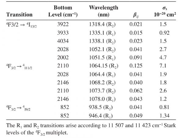
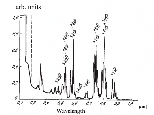
FIGURE 03 Absorption spectra of an Nd:YAG crystal
The intensity of the absorption lines is dictated by the cross section of the transitions. In addition to the neodymium ions, the pumping light can be absorbed into the matrix of the YAG crystal. The YAG matrix is transparent in the range of 240-5500nm. Therefore, in the range of visible and near-infrared radiation, where the strongest absorption lines are located, the absorption by the matrix is not relevant. The matrix absorption spectrum may be caused by impurities or defects. In the light of these remarks, we shall consider the absorption spectrum of Nd:YAG crystals, shown in Figure 03. As can be seen from the spectrum, the basic absorption is given by five main peaks, arising from transitions to the following pump levels:
- 4F3/2: λ≈880nm;
- 4F3/2+ 2H9/2∶ λ≈810nm;
- 4F7/2 + 4S3/2: λ≈750nm;
- 2G7/2 + 4G5/2: λ≈580nm;
- 2K13/2 + 2G7/2 + 4G9/2: λ≈520nm.
The other absorption peaks have a small effect on the laser pumping process because of their small cross sections. The two most intense peaks are located in the spectral range of the basic pump source. The ultraviolet area is characterized by absorption peaks 360 and 260nm while the wing of the matrix absorption begins at 400nm and rises strongly to 240nm (i.e. the absorption edge of the transparent crystal/matrix). As the pump light absorbed by the matrix does not contribute to useful laser radiation and only results in heating, the ultraviolet pumping radiation in real lasers is absorbed by a special light filter, to prevent it from impinging upon the Nd:YAG laser rod. The UV filter is necessary to avoid the generation of colour centres from residual impurities and defects and, in particular, from iron ions. Such colour centres absorb pump and laser radiation and sharply reduce the efficiency of the laser.
1.5 Properties of the Basic 4F32→4I11/2 Transition at 1064 nm
The Nd:YAG emission line at 1064.15nm offers the maximum emission cross section and efficiency. It is possible, however, to obtain oscillation at other wavelengths by inserting etalons or dispersive prisms in the resonator, by utilizing a specially designed resonant reflector as an output mirror or by employing highly selective dielectrically coated mirrors. These elements suppress laser oscillation at the undesirable wavelength and provide optimum conditions at the desired wavelength. With this technique, over 20 transitions have been made to lase in Nd:YAG (Table 02).
The 1.064 and 1.06l um lines of the 4F3/2 → 4I11/2 provide the lowest threshold in Nd:YAG. At room temperature, the 1.064 um line R2 → Y3 is dominant, while at low temperatures, the 1.061 um line R1, → Y1, has the lower threshold. If the flashlamp-pumped laser crystal is cooled, additional laser transitions are obtained, most notably the 0.946 um line. Diode-pumped Nd:YAG lasing is very effective at the 0.946 um line for a temperature of 300 K (Table 08).
The 1.064 and 1.061 um lines are caused by two transitions close in frequency: 512, between levels 11 507cm-1 (4F3/2) and 2110cm-1 (4I11/2) and 411, between levels 11 423cm-1 (4F3/2) and 2028cm-1 (4I11/2) (Figure 02 and Table 02). The energy and wavelengths of these transitions are (i) 512: 9397cm-1 (1064.17nm) and (ii)411: 9395cm-1 (1064.4nm). The linewidth for room temperatures is equal to 6.5cm-1, which appreciably exceeds the distance between them (2cm-1). Therefore, the line contours are strongly blocked by each other, hence form-ing a total contour, which is only slightly distinguishable from a Lorentzian function. The intensity of the 411, line is weaker than the 512 line (σ4l1 ≃ 1.9×10⁻¹⁹cm2, σ4l2 =7.1×10⁻¹⁹cm2) and, consequently, the centre of the total line is closer to the centre of the stronger line corresponding to a wavelength of 1064.15nm. The effective cross section slightly exceeds the cross section of the stronger line at 8.8×10⁻¹⁹cm2. At room temperature (300 K), the Maxwell-Boltzmann fraction in the upper Stark sublevel is 0.427 for Nd:YAG.The effective stimulated emission cross section is the spectroscopic cross section multiplied by the occupation of the upper laser level relative to the entire 4F3/2 manifold population.
Heating the crystal displaces the line to a longer wavelength. For temperature intervals of ±60℃, which are of interest for practical applications, this displacement can be well described by a linear function with a slope of dλ/dT=5×10-3nm K-l and the line centre is located at 1064.15nm at room temperature (300K).
1.6 Concentration Quenching of Emission for High Neodymium Doping Levels
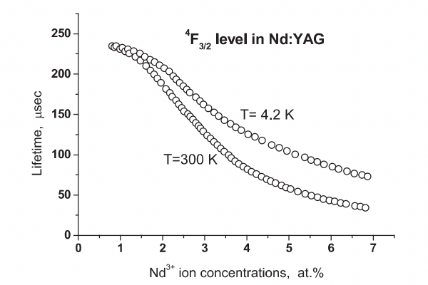
For Nd lasers to function effectively, the activator ions should absorb the maximum amount of pump radiation. As the absorption lines of rare-earth ions in crystals are weak, increasing the activator concentration is of interest. However, at an increased activator concentration, we encounter the phenomenon of concentration quenching of the emission, which appears as a short non-exponential fluorescence decay and a fall in the quantum efficiency.In Figure 04a. the dependence of the 4F3/2, level lifetime on the Nd3+ concentration in the YAG crystal is shown. Up to 1 at%, the lifetime does not depend on concentration and is about 250 us; at CNd > 1 at%, there is a sharp reduction in lifetime. Similarly at CNd = 1 at%, the maximum emission intensity is observed (Figure 04b.). This drop at very low concentrations is connected with a reduction in absorbed pump light and at large concentrations with the fall in the quantum efficiency due to non-radiative relaxation. The concentration of neodymium (by at%)in YAG has been limited to 1.0%-1.5%. Higher doping levels tend to shorten the fluorescence lifetime, broaden the linewidth and cause strain in the crystal, resulting in poor optical quality. There is an optimum concentration CNd=1 at% corresponding to the minimum threshold for laser generation.
The nature of the concentration quenching of the emission, as previously specified, is connected to the interaction of Nd3+ ions with each other. Two closely located Nd3+ ions are coupled with each other by a dipole-dipole interaction, which strongly depends on distance (W ≃ 1/R-6). A pair of Nd3+ ions is capable of creating an additional channel for non-radiative relaxation of Nd3+ ions from the 4F3/2 level. The performance of an Nd:YAG laser can be somewhat improved by choosing the optimum Nd concentration. As a general guideline, it can be stated that a high doping concentration (approximately 1.2 at%) is desirable for Q-switched operation because this will lead to high energy storage. For continuous-wave (cw) operation, a lower doping concentration (0.6-0.8 at%) is usually chosen to obtain good beam quality and the minimum lasing threshold.
 |
 |
| (a) | (b) |
FIGURE 04 (a) Lifetime dependence of 4F3/2 level on Nd3+ ions concentration in YAG crystals. (b) The concentration quenching of the 4F3/2 level emission.
The design, fabrication and properties of many lasers based on different Nd3+-doped crystals are described in the papers presented at Advanced Solid State Lasers conferences [2-11]. The performance of a laser-diode-pumped solid-state laser is superior to that of a flashlamp-pumped solid-state laser includ-ing such characteristics as high efficiency, high beam quality and high output power stability. It is more difficult to develop a high-power laser with high output parameters. Diode-pumped solid-state lasers operating at high cw power levels are attractive light sources for various applications ranging from material processing to sophisticated fundamental physics experiments.
A design for a diode-pumped cw Nd:YAG laser [12] with an output power of up to 750 W is shown in Figure 05. The out-put power of the laser at 1.06 um is plotted in Figure 06.The design features and performance are summarized in Table 03.
A multi-kilowatt, high brightness, diode-pumped laser for precision laser machining [13] is presented schematically in Figure 07 and Table 04. The laser gain uses a 0.5×3.6×17cm Nd:YAG slab. Figure 08 shows the output-input energy of a high-power module containing the zigzag Nd:YAG slab pumped by a stacked quasi-cw diode array. The zigzag geometry is already well known to minimimize thermal lensing. The Brewster-cut slab allows nearly fulfilled minimizing regions of unextracted gain due to the slab geometry, which means that no coating is required on the crystal end faces. The input faces of the slab are anti-reflection coated and cooled directly with water. An unstable resonator using a hyper-Gaussian variable reflectance mirror enables the laser to run in a single transverse mode with the beam quality limited by a single pass of the gain modules.
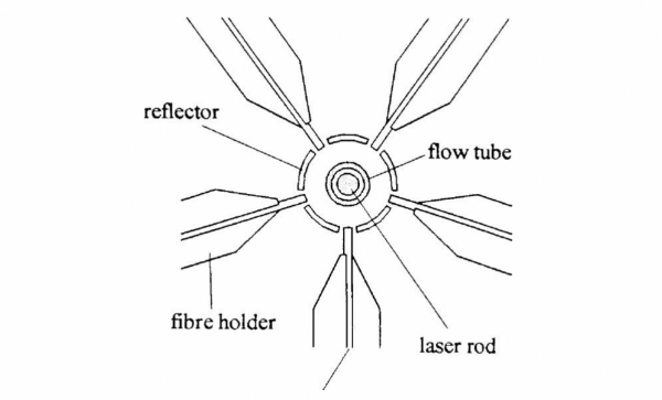
FIGURE 05 A diode pumped Nd:YAG laser
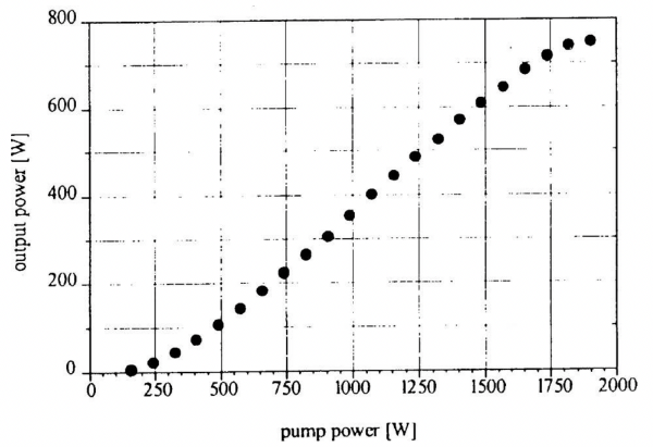
FIGURE 06 Output power at 1.06 pm
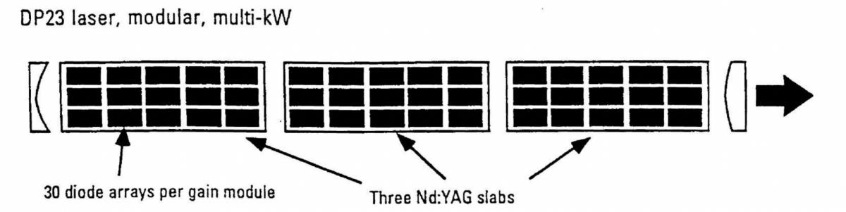
FIGURE 07 Laser diode pumping and resonator configuration of an Nd:YAG laser
Table 03 Parameter of a Side-Pumped Nd:YAG Laser
The resonator magnification was 1.5 and the cavity length was approximately 1m. Figure 09 summarizes the beam quality of the laser as a function of output power.
A high brightness mode-locked Nd:YAG end-pumped zigzag slab laser has been developed with a mode-locked master oscillator and high-power amplifier using a novel architecture [14]. The laser emitted 150 W of linearly polarized power with an average M2 beam quality of 1.25. A schematic layout of the laser system is shown in Figure 10. The gain module uses a 5.6×1.7×67mm (height × thickness × length) composite zigzag slab. The central 49nm length of the slab is 0.2% doped Nd:YAG with 9mm long, diffusion-bonded, undoped YAG end caps on each side to reduce end effects by confining heat generation to the centre section.
Table 04 Multi-Kilowatt, High Brightness, Diode-Pumped Nd:YAG Laser
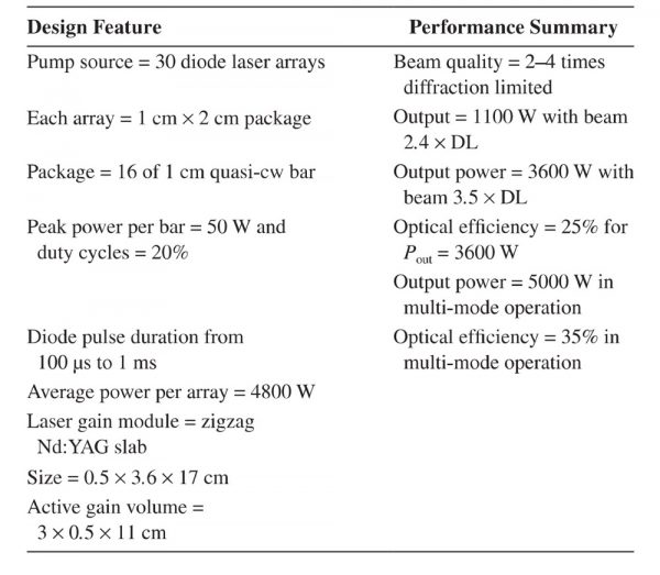
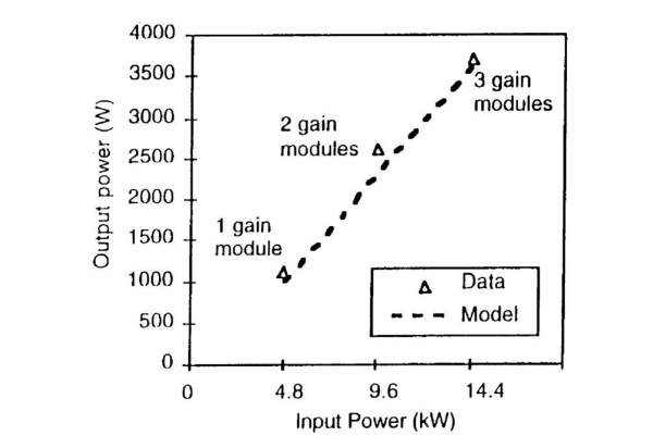
FIGURE 08 Laser output as a function of diode power
The slab ends are cut at 45° and anti-reflection coated for 1064nm. The total internal reflection (TIR) faces have 3 um thick, SiO2, evanescent wave coatings, which allow the faces to be contacted and conduction cooled. Water-cooled copper microchannel coolers are thermally contacted to the slab’s TIR faces using a low thermal resistance interface.
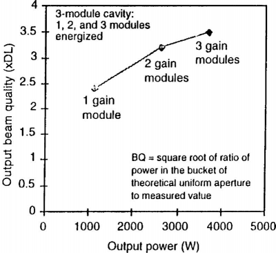
FIGURE 09 Laser beam quality as a function of output power
The slab is pumped from both ends by 805nm cw diode arrays. Microlenses collimate the fast axis of each diode bar and a lens duct with a 93% throughput concen-trates the pump light to a 1.5×5mm area. The diode light is injected through the first TIR footprint, where the evanescent wave coating also acts as an anti-reflection coating at 805nm. The pump light undergoes a TIR reflection from the 45° input face of the slab and is guided down the length of the slab by the TIR for efficient and uniform end pumping. Approximately 85% of the total pump light is absorbed in the slab. The total diode pump power is 1200 W and the Nd:YAG laser operated with an optical efficiency of 12.5%.
Efficient, cw-pumped TEM00 mode infrared beam sources are of interest in both industrial and scientific applications,e.g. optical communications, material processing, gravitational wave detection and so on. Furthermore, cw-pumped TEM00 mode of 1064nm beam sources is in high demand in the information technology field, where frequency-converted ultra-violet or visible high-repetition-rate Q-switched laser beams are used for drilling or trimming the printed circuit boards mounted in mobile phones and computers. Various attractive schemes for TEM00 mode cw diode-pumped Nd:YAG lasers have been proposed [15-18]: their highest single-transverse-mode power was less than 100 W with an electrical efficiency of less than 10%.
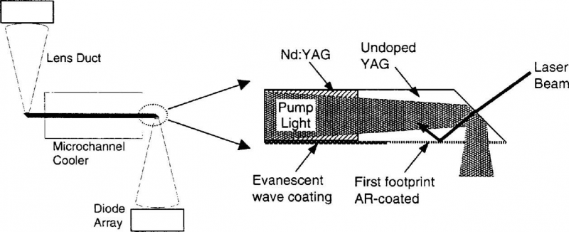
FIGURE 10 Schematic diagram of a condition-cooled, end-pumped zigzag slab architecture
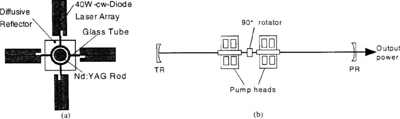
FIGURE 11 Schematic diagram of (a) the pump module and (b) the resonator configuration
CW 153 W output power in the TEM00 mode at 1064nm generated by a laser-diode-pumped Nd:YAG rod laser with an electrical efficiency of 10.9% and beam quality M2=1.18 is described in Ref. [19]. Figure 11 shows the laser design. A quartz 90° polarization rotator was placed between two uniformly pumped Nd:YAG rods for polarization-dependent bifocusing compensation [20]. The pump heat consisted of two modules. Each module contained four I cm long linear cw diode arrays (808nm wavelength and 40 W average output power). One module was rotated 22.5° from the other around the optical axis to produce a uniform pump-light distribu-tion within the rod cross section. Each Nd:YAG rod (4mm in diameter and 70mm in length, with 0.6% Nd doping) was surrounded by a flow tube and a diffusive reflector. In Figure 12, a high-order (M2=40) laser performance in two mode-multi-transverse and TEM00 at 1064nm operation are compared. In both cases, the transmittance of the output coupler was 20%-25%.
Based on the calculation reported in Ref.[18], the 950-mm long concave-concave resonator was designed to provide stable operation near the highest diode pump power of 700 W. A maximum TEM00 output power of 153 W was generated with 682 W total diode pump power and 1409 W electrical input power into the laser diodes, corresponding to an electrical efficiency of 10.9% and an optical-to-optical conversion efficiency of 22.4%.
The use of diode-laser bars as efficient high-power pump sources for end-pumped Nd:YAG solid-state lasers is now well established [21-24]. Slope efficiencies reaching 50%-60% at 1064nm have been reported for end-pumped Nd:YAG lasers by fibre-coupled diodes or a beam-shaped diode bar, the maximum attainable power was limited by the rod diameter and space for the diode.
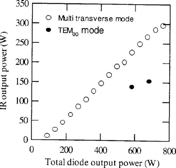
FIGURE 12 Multi-transverse and TEM00 mode laser performances
The side pumping has been favourable for scaling to a high output power, for it is convenient to use a large number of diode arrays and reduce the thermal loading problems, but the slope efficiency is reduced to 25%-40%; the lower slope efficiency is usually caused by imperfect matching between the laser mode volume and the diode pumping volume.
2. Polycrystalline Nd:YAG Ceramic Laser
Highly transparent nanocrystalline Nd:Y3Al5O12 (Nd:YAG)is a new type of inorganic laser media for a new generation of solid-state lasers. A polycrystalline ceramic laser material is an aggregate of crystalline grains, each randomly oriented with respect to neighbouring grains. Polycrystalline Nd:YAG has received much attention since the quality of ceramics Nd:YAG has been improved greatly and highly efficient laser oscillation can be obtained [25-32]. Compared to single crystal Nd:YAG, the ceramic Nd:YAG laser material has several advantages:
- its ease of fabrication;
- it is less expensive;
- large sizes and high neodymium concentrations can be fabricated;
- it has a multi-layer and multi-functional ceramic structure and
- it can be mass produced.
The first solid-state laser based on a ceramic polycrystalline fluoride material (Dy:CaF) was reported in the middle of the 1960s. But only in the last decade have ceramic Nd:YAG laser materials received much attention, after highly transparent nanocrystalline Y3Al5O12 (YAG) doped with Ln activators, in particular Nd ions, were developed (see, for example, Refs.[25-27]).The first Nd:Y3Al5O12 (Nd:YAG) ceramic laser was reported in 1995 [28]. High-power and highly efficient lasers with laser-diode pumping were constructed [29-33]from ceramics of Nd:YAG.
The room-temperature absorption spectra of ceramics and single-crystal Nd:YAG are shown in Figure 13. For both single-crystal and ceramic Nd:YAG, the absorption peaks are centred at 808.6nm.
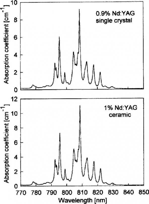
FIGURE 13 Absorption spectrum:single crystal 0.9% Nd:YAG and ceramic 1% Nd:YAG
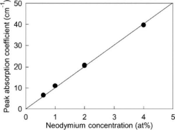
FIGURE 14 Peak absorption coefficient of ceramics Nd:YAG around 808nm versus neodymium concentration
The FWHMs (full widths at half maximum) of the absorption coefficients are both 1.04nm. Room-temperature absorption spectra for 0.6%,2% and 4% ceramics Nd:YAG have also been measured. Not much difference has been observed except that the absorption coefficient increases with an increase in Nd3+ concentration. Figure 14 shows the peak absorption coefficient of ceramic Nd:YAG around 808.6nm versus neodymium concentration. From this figure, one can see that the relationship between the peak absorption coefficient and neodymium concentration is linear.
Figure 15 shows the room-temperature fluorescence spectrum for the 4F3/2 → 4I11/2 transition of a 1% Nd:YAG single crystal and ceramic, respectively. To have a clear comparison, the fluorescence spectra for the single crystal and ceramic were normalized and put together. From this figure, these two spectra are almost identical. The main emission peak is at 1064.18nm.The FWHM is 0.78nm.
Emission spectra for 0.6%,2% and 4% Nd:YAG ceramics have also been measured [29]. A small wavelength redshift has been observed with increasing concentration because of a slight change in the crystal field.
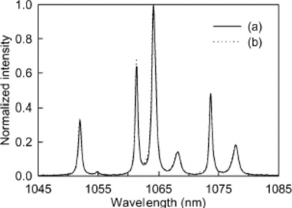
FIGURE 15 Fluorescence spectrum: (a) ceramic 1% Nd:YAG and (b) single crystal 0.9% Nd:YAG
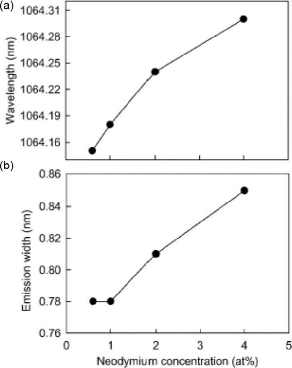
FIGURE 16 (a) Fluorescence redshift and (b) FWHM at 1064mm versus neodymium concentration
Figure 16a shows the main fluorescence peak spectra at 1064nm for 0.6%, 1%, 2% and 4% Nd:YAG ceramics, respectively.
The four emission peaks are centred at 1064.15,1064.18, 1064.24 and 1064.30nm for 0.6%, 1%, 2% and 4% Nd:YAG ceramics, respectively. The redshift from 0.6% to 4% Nd:YAG ceramics is 0.12nm. Because of the fluorescence quenching effect, the fluorescence emission linewidth at 1064nm is also slightly broadened with concentration increases greater than 1%. Figure 16b shows the FWHM of the 1064nm fluorescence peak. The FWHMs are 0.78, 0.78, 0.81 and 0.85nm for 0.6%, 1%, 2% and 4% Nd:YAG ceramics, respectively. The linewidths for 0.6% and 1% Nd:YAG ceramics are identical. This means that the fluorescence quenching effect is very weak for neodymium concentrations less than 1%, which is similar to that of a single crystal.
Figure 17 shows the fluorescence lifetime of single crystal and Nd:YAG ceramics versus neodymium concentration.
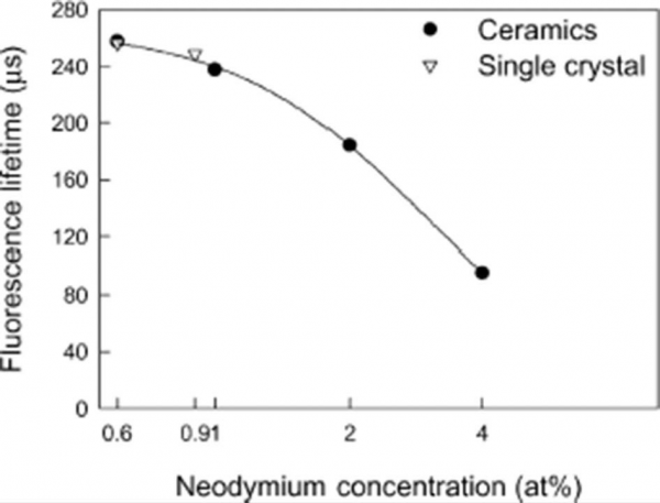
FIGURE 17 Fluorescence lifetime of ceramic and single-crystal Nd:YAG versws neodymium concentration.
The full curve is the fitted curve for the ceramic fluorescence lifetime
The fluorescence lifetime for a single-crystal 0.6% Nd:YAG (procured from Litton-Airtron Inc.) and that for a single-crystal 0.9% Nd∶YAG are 256.3 and 248.6 μs,respectively.
Fluorescence lifetimes of 257.6,237.6,184.2 and 95.6 μs have been measured, respectively, for 0.6%, 1%, 2% and 4% ceramics Nd:YAG.These data agree well with the results in Ref.[1]. The fluorescence lifetime decreases dramatically when the neodymium concentration exceeds 1%. The fluorescence lifetimes for the 0.6% doped single crystal and the ceramics are almost identical (only 1.3 μs difference). The fluorescence lifetime difference between 0.9% Nd:YAG single crystal and 1% Nd:YAG ceramic is ll us. We could predict that for the same concentration for single-crystal and ceramic Nd:YAG, for example, a concentration of 0.9%, the lifetime difference should be less than ll us. From the fitted curve for the ceramic fluorescence lifetimes, the lifetime for the 0.9% Nd:YAG ceramic is 244.2 us, which is only 4.4 us different from that of the single-crystal 0.9% Nd:YAG [29].
A 1.46kW Nd:YAG ceramic laser was demonstrated by the Toshiba Corporation, Japan [34]. The optical-to-optical conversion efficiency is 42%. The dependence of output power on pump power is shown in Figure 4.18. The data on the single-crystal Nd:YAG laser are also shown on the same graph to allow a comparison. An output power of 1.72kW was obtained for the single-crystal laser, with an optical-to-optical conversion efficiency of 49%.
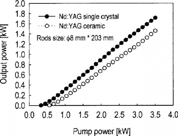
FIGURE 18 Laser outputs of ceramic and single-crystal Nd:YAG lasers as a function of pump power
Although the laser efficiency of the ceramic Nd:YAG laser is still less than that of the single-crystal Nd:YAG laser, it shows that it could possibly be used in industry in the near future.
Nanocrystalline Nd:YAG ceramics, as the new generation of laser materials, will before long become a very good alternative to the widely used Nd:YAG single crystals for different types of solid-state lasers, including multi-kW industrial lasers.
3. Nd:YLF Laser Crystal
Nd:YLF is a good candidate for certain specialized applications because the output is polarized and the crystal exhibits a lower thermal birefringence [35,36]. Nd:YLF has a higher energy storage capability (due to its lower gain coefficient) compared to Nd:YAG and its output wavelength matches that of phosphate Nd:glass; therefore mode-locked and Q-switched Nd:YLF lasers [37] have become the standard oscillators for the large glass lasers employed in fusion research.
Some of the important physical properties of Nd:YLF are listed in Table 01, together with its optical and laser parameters. Nd:YLF is grown utilizing a modified CZ technique. The as-grown crystals are then processed into laser rods or slabs.
The favourable features of Nd:YLF are:
- a large product of the stimulated emission cross section and lifetime for a low cw threshold,
- high-power, low-beam-divergence, efficient single-mode operation,
- high average power Q-switched operation at a moderate repetition rate,
- linearly polarized resonators for Q-switching and frequency doubling,
- potential uniform mode for large diameter rods or slabs and
- the 1053 nm output matches the gain curves of Nd:glass and performs well as an oscillator and preamplifier for this type of laser.
4. Nd:Vanadate Laser Crystals
For small and efficient diode-laser-pumped solid-state laser systems, it is desirable to decrease the requirement for temperature control of the diode-laser pump and to increase the tolerance in the wavelength selection. Therefore, it is necessary that the laser material features a high absorption coefficient and a large absorption linewidth. Disordered crystals, for instance, offer broad absorption lines but have the disadvantage of low cross sections due to the inhomogeneous broadening of the transitions. Therefore, the advantage of low-temperature sensitivity of the pumping process and the corresponding increased tolerance in pump-wavelength selection is corre-lated in such crystals with decreased inhomogeneous emission cross sections.
In vanadate crystals like Nd:YVO4 [38-41] and Nd:GdVO4 [42], both broad homogeneous absorption lines and homogeneous emission lines feature high peak cross sections (Table 05), As we know, the accidental degeneracy of the 4F3/2 level in GdVO4. enhances the emission cross sections because the spectra condense into fewer emission lines [4].
Table 05 Comparison of Nd:YVO4 and Nd:GdVO4
4.1 Preparation of the Nd:YVO4 and Nd:GdVO4 Crystals
Laser quality crystals of vanadate doped with neodymium can be grown by the CZ technique. Yttrium vanadate and gadolinium vanadate belong to the group of oxide compounds crystallizing in a ZrSiO4 structure with the tetragonal space group I41/amd. The fourfold symmetry axis is the crystallographic c-axis. Perpendicular to this axis are the two undistinguishable a- and b-axes. The rare-earth ion, which is surrounded by eight oxygen atoms, has site symmetry 42m.
In comparison with YVO4, the replacement of Y3+ ions by the larger Gd³+ ions increases the distances between the dodecahedral lattice sites. This decreases the ion-ion interactions between neighbouring ions and also makes the segregation coefficient of Nd3+ ions closer to unity.
The YVO4 and Nd:GdVO4 crystals are grown by the CZ method along the c-axis or a-axis. As growth parameters it used a pulling rate of 1-2mm h-l, a rotation rate of 10-30 rev min-l and an atmosphere of nitrogen containing 2% oxygen by volume. The crystals were then annealed at 1200℃ for 10h in air. The melting point of Nd:GdVO4 was measured with an optical pyrometer to be 1800℃±20℃.
4.2 Absorption and Emission of Nd:GdVO4
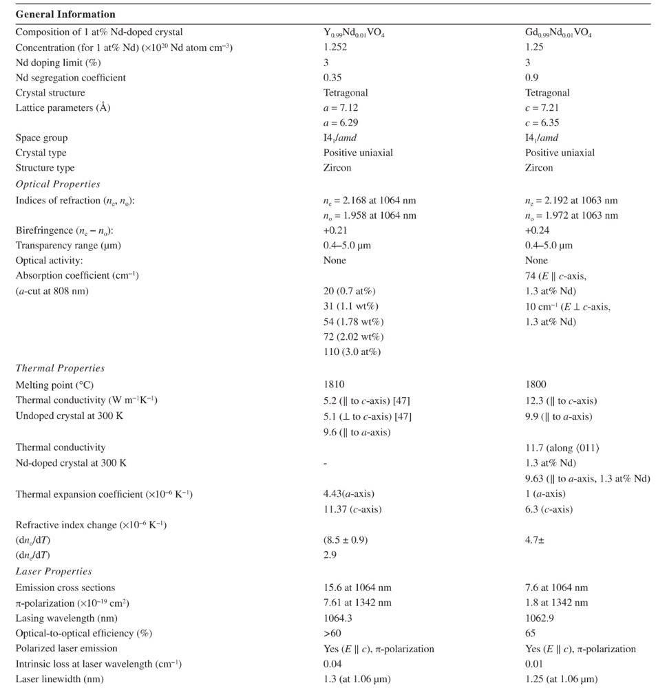
The uniaxial crystal Nd:GdVO4, shows strong polarization-dependent absorption transitions due to the anisotropic crystal field. At 808.4 nm, the peak absorption coefficient in π-polarization is 78 cm-1 for a 1.2% neodymium doping level, resulting in an effective absorption cross section of 5.2×10⁻¹⁹cm2[42,43]. For σ-polarization, the absorption coefficient is only 17 cm-1. The absorption spectra as a function of wavelength for both polarizations are shown in Figure 19.
The half-width of the absorption at 808.4nm is 1.6nm. At the same neodymium concentration, the absorption coefficient of Nd:GdVO4, is seven times higher and the transition line is 80% broader in comparison with Nd:YAG.
FIGURE 19 Absorption spectra for Nd:GdVO4 π-and σ-polarization.
The absorption spectrum of Nd:YAG is shown for comparison.
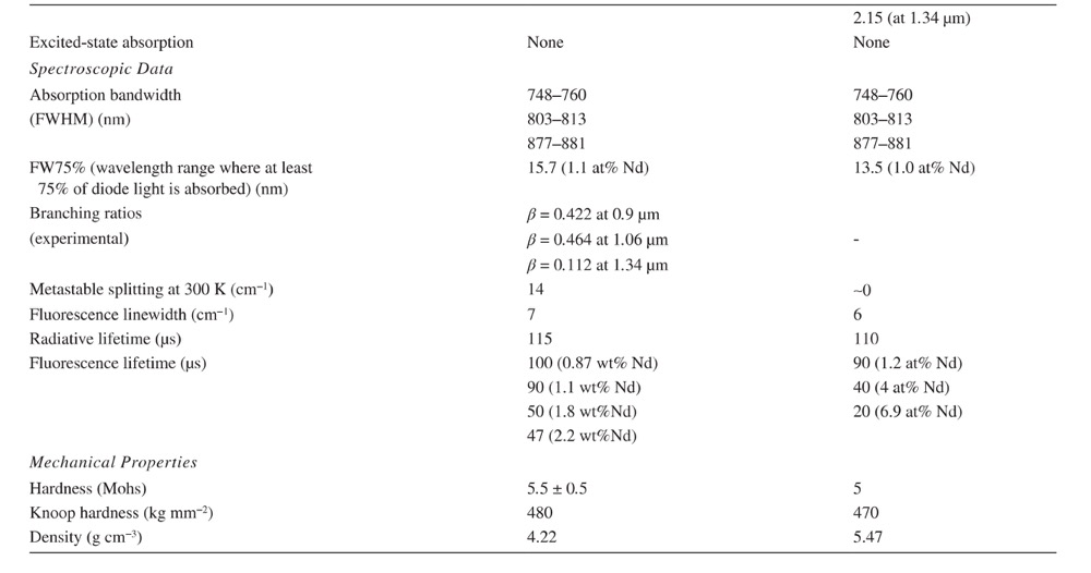
Figure 20 shows an enlarged plot of the 4F3/2 → 4I11/2 in π-polarization in comparison with a corresponding spectrum of Nd:YAG. The total Stark splitting of the 4F3/2 multiplet is about one-third of that in Nd:YAG.In addition, the number of transition lines is reduced in Nd:GdVO4. Transition pairs, resulting from the 4F3/2 splitting (indicated by arrows in the Nd:YAG spectrum), are not assignable in the spectrum of Nd:GdVO4. This leads to the assumption that the upper laser level 4F3/2 is completely degenerate, resulting in a reduction of transition lines by a factor of two, which could be verified by the measurements at 12 K. For completeness the detected energy levels derived from corresponding 77 K spectra of Nd:GdVO4 are listed in Table 06.
FIGURE 20 Fluorescence spectra of the 4F3/2 → 4I11/2 in π-polarization in comparison with Nd:YAG at 300 K
Table 06 Splitting of the 4I and 4F Terms of Nd3+ in GdVO4 at 77 K

We do not know other laser crystals with 4F3/2 degeneracy. Nd:YVO4, which is a similar compound, has a 4F3/2 splitting of 18cm-1. Therefore, the effective emission cross section, in the case of Nd:GdVO4, is identical to the atomic emission cross section. This is illustrated in Figure 21, which shows the splitting of the materials Nd:YAG, Nd:YVO4 and Nd:GdVO4, by the transition lines of the 4F3/2 level, into a single level of the 4F3/2 multiplet.
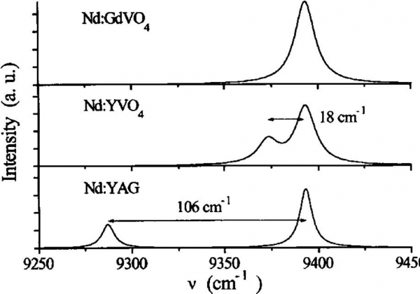
FIGURE 21 Merging of transition lines for the three crystals Nd:YAG, Nd:YVO4, and Nd:GdVO4 at 300 K.
A splitting of the 4I3/2 level in Nd:GdVO4 could not be detected.
4.3 Nd:YVO4 and Nd:GdVO4 Lasers
Neodymium-doped gadolinium vanadate (Nd:GdVO4) is an attractive and very efficient laser material for diode pumping and has been receiving considerable attention [42-46]. Compared with Nd:YAG crystal, Nd:GdVO4 has a sevenfold larger absorption cross section(5.2 × 10⁻¹⁹cm2, E||c) and a threefold larger emission cross section at 1.06 um (7.6 x 10⁻¹⁹cm2, E||c).More importantly,the Nd:GdVO4 thermal conductivity (12.3 W m-l K-l, direction ll to the c-axis) is very good and comparable to that of YAG. Such unique spectroscopic and thermal properties make the Nd:GdVO4 crystal a promising substitute for Nd:YAG diode-pumped compact solid-state lasers[48-50].
The laser output power [48] of an Nd:GdVO4 at 1.06mm was 14.3 W at the highest pump power of 26 W, the light-light conversion efficiency was 54.8%, the pumping threshold was 0.32 W and the slope efficiency was 62%. Figure 22 gives a schematic diagram of the laser and Figure 23 shows its input-output power.
Passively Q-switched laser output of an Nd:GdVO4 crystal at 1.06 μm has been demonstrated [49].
An actively acousto-optical Q-switched diode-pumping Nd:GdVO4 laser (Figure 24) is described in Ref.[48]. The average Q-switched (60kHz) laser output power at 1.06 um was 7.3 W at a pump power of 19 W, the pumping threshold was 1.3 W, the optical-optical conversion efficiency was 38.1% and the average slope efficiency was 42.9%.
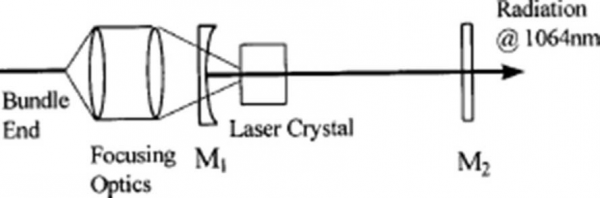
FIGURE 22 Schematic diagram of a diode-pumped Nd:GdVO4 crystal lasing at 1063nm. M1, M2, mirrors
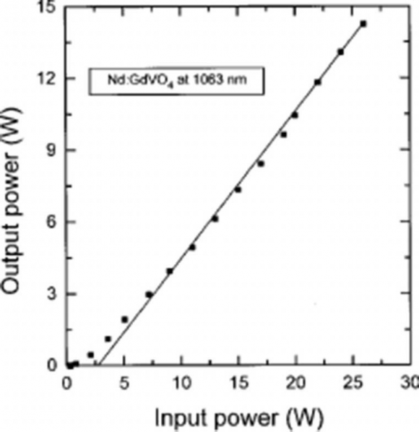
FIGURE 23 Output power of an Nd:GdVO₄ crystal at 1063nm
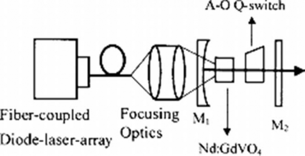
FIGURE 24 Schematic diagram of an end-pumped Q-switched 1.06 um Nd:GdVO₄, laser. A-O, acousto-optical; M1, M2, mirrors
Some important parameters of an Nd:GdVO4. crystal have been calculated or estimated [48]: dn/dT= 4.7×10⁻⁵ K-1, material constant=3.5×10⁻⁶m2s-1, FOM of the thermal stress resistance > 5.73 W cm-l and power per unit length at the stress limit=51.6 W cm-l.
New-generation diode pump sources allow end-pumped cw lasers to achieve gain levels previously reached only in quasi-cw diode-pumped systems. A very effective cw pumping oscillator layout is shown in Figure 25 [50]. The short cavity lengths and high pump intensity ensured very short pulse Q-switched operation (Table 07). The end-pumped Nd:YVO4. (or Nd:YAG or Nd:YLF)lasers with single-pass small-signal gain G=10 produce Q-switched output at the 16 W level in 6 ns pulses at 20Hz (Table 07).
One of the major advantages of Nd:YVO4 (Nd:GdVO4) is its ability to retain short pulse output even at a very high peak rate frequency (prf). The Nd:YVO4 demonstrated sub-20 ns pulses at 100kHz prf. However, the usual laser scheme based on Nd:YVO4 and Nd:GdVO4 performs poorly at lower prf; while Nd:YAG and Nd:YLF perform well at 10kHz, the Nd:YVO4 drops in output power by 50% compared to operation at 100kHz. The use of short-cavity laser design on Figure 26 allows highly efficient Q-switched operation with a very low threshold at low and high prf to be obtained.
Now many companies in the world produce commercial low and middle-power lasers based on vanadate crystals. A≈diode-pumped laser with two Nd:YVO4 rods and four diode bars produces an output power of about 35 W at 1064nm, 20 W at 532nm and 8 W at 355 nm——all with a beam quality M2<1.3 (Spectra-Physics, Tucson, AZ, USA).
Diode-pumped Nd:GdVO4 lasers at 1.06 um have demon-strated an output power of ~25 W with a slope efficiency of 60% with beam quality M2=1.55.In such lasers, vanadate crystals about 3×3×4mm in size and cut with the a-axis parallel to the optical axis of the laser system are used. A diode-pumped quasi-three-level Nd3+ laser operating on 4F3/2 → 4I9/2 has been realized for Nd:YAG, Nd:YAlO3, Nd:YVO4 and Nd:GdVO4 crystals (Table 08). The three-level scheme for Nd3+ lasing in a GdVO4 host is shown in Figure 27.

FIGURE 25 A high-gain end-pumped Nd:YVO4, laser
Table 07 TEM00 Laser Properties of Q-switched Operation
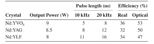
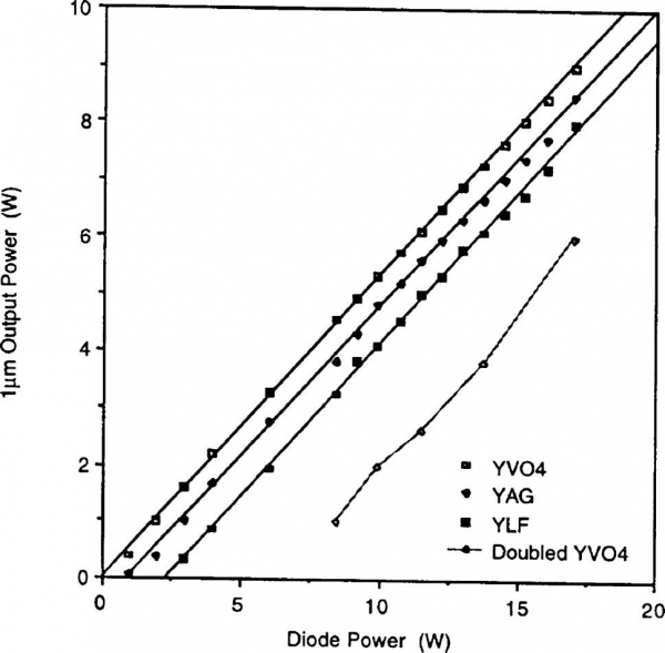
FIGURE 26 Performance characteristics of an actively Q-switched end-pumped laser for a short cavity design
Table 08 Performance of cw Diode-pumped Quasi-Three-Level Lasers
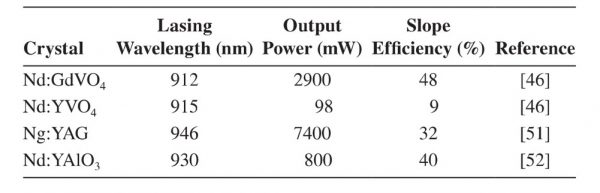
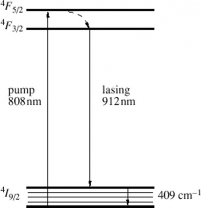
FIGURE 27 Diagram of the levels and energy transformation in Nd:GdVO4 crystals during lasing at 912nm upon the 4F3/2 → 4I9/2 transition
5. Nd:Cr:GSGG and Nd:Cr:YSGG Crystals
Soon after the invention of the Nd:YAG laser, attempts were made to increase the efficiency in transferring radiation from the pump source to the laser crystal by utilizing a second dopant called a ‘sensitizer’. A particularly attractive sensitizer is Cr³+[53,54] because the broad absorption bands of chromium can efficiently absorb light throughout the whole visible region of the spectrum (Figure 28).The concept of improving efficiency by co-doping an Nd:laser crystal with Cr³+ ions is based on transferring excitation [55,56], absorbed by the broad Cr³+ absorption bands, over to the Nd³+ ions. No improvement was achieved with the host crystal YAG because all the Cr³+ excitation was deposited in the 2E level and the spin-forbidden nature of the 2E → 4A2 transition resulted in an inefficient transfer process.
However, measurements at the author’s laboratory have shown that nearly 100% transfer efficiency could be achieved in the co-doped garnet crystal Gd3Sc2Ga3O12 (GSGG) and Y3Sc2Ga3O12 (YSGG). Unlike YAG, a large percentage of the Cr³+ excitation in GSGG and YSGG appears in the 4T2 state and non-radiative transfer to Nd³+ ions can occur via the 4T2–4A2 transition, which is spin-allowed and has a good spectral overlap with the Nd³+ levels (Figure 29).
Experiments performed in some studies [53-56] showed, with the flashlamp-pumped operation, nearly a factor-of-three improvement in slope efficiency for the doubly doped garnet compared to an Nd:YAG crystal. For an Nd:Cr:YSGG laser rod 6.3mm in diameter and 100mm in length, we have achieved an output energy of 2J, electrical efficiency of 7.7% and a slope efficiency of 8.8%, which is the highest slope efficiency yet reported for flashlamp-pumped solid-state lasers.
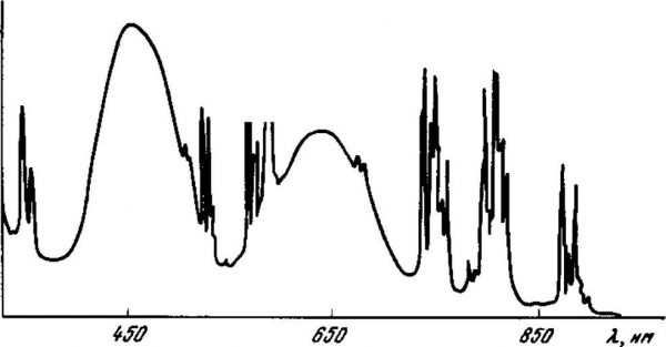
FIGURE 28 Absorption spectra of an Nd:Cr:GSGG crystal
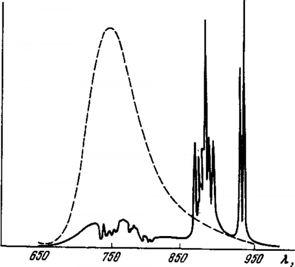
FIGURE 29 Emission spectra of Cr:GSGG crystals (dotted line) and emission spectra of Nd:Cr:GSGG crystal (full) at temperature 300K
It was found that the pumping efficiency improvement is not a strong function of the Cr concentration for the range 1-2×1020cm-3. The higher pump efficiency of Nd:Cr:GSGG and Nd:Cr:YSGG does not automatically translate into better system performance because Nd:Cr:GSGG does exhibit much stronger thermal focusing and stress birefringence, compared to Nd:YAG (see Tables 01 and 09). The absorption efficiency and heat deposition rate for the Cr:Nd:GSGG rod are almost three times those of Nd:YAG, a consequence of the broad red and blue absorption bands of the Cr3+ sensitizer. As a consequence, the thermal focusing power as a function of lamp input power has been reported to be several times larger in Cr:Nd:GSG or Cr:Nd:YSGG than in Nd:YAG.Therefore, if beam brightness is the criterion, rather than output energy, some of the advantages of Cr:Nd:GSGG and Cr:Nd:YSGG are offset, particularly at medium average powers. Now Nd:Cr:GSGG and Nd:Cr:YSGG laser rods are widely used in compact military range-finders. Measurements have shown that under single-shot and low-repetition-rate operation, a factor of two higher beam brightness is achieved in a GSGG or YSGG system compared to a YAG system.
Active elements manufactured from Nd:Cr:GSGG and Nd:Cr:YSGG crystals are optimum materials for low- and medium-power flashlamp-pumped lasers with low repetition rates of up to several cycles per second. The advantages of YSGG and GSGG crystals compared with YAG crystals are lost when large-size elements are used because of the worse thermal characteristics of Nd:Cr:GSGG and Nd:Cr:YSGG crystals[57,58].
High-optical-quality Nd:Cr:GSGG and Nd:Cr:YSGG crystals up to 13cm in diameter and 23cm long are grown com-mercially in Russia and the USA by the CZ technique [57].
6. Nd:LSB Crystal
Neodymium-doped borate scandium lanthanum (Nd:LaSc3(BO3)4 or Nd:LSB) is one of the most efficient laser crystals for diode pumping as well as for flashlamp pumping [58,59]. It is a new laser crystal with improved spectral properties stipulated by the possibility of the introduction of high Nd³+ concentrations (up to 50 at%) into the crystalline host.
These properties make the Nd:LSB crystal indispensable in the design of low-power (up to 150mW at 531 nm), highly efficient compact diode-pumped solid-state laser systems because they allow the effect of temperature drift of the wavelength of the pumping laser diode to be reduced and the stability of the radiated laser frequency to be increased because of the wide absorption line of Nd ions at the 808nm wavelength. The maximum absorption and radiation cross section are similar to those of Nd:YAG but the bands are five times wider. The absorption coefficient of 10 at% Nd3+:LSB crystals is three times higher than that in Nd:YAG crystals. This allows Nd:LSB active elements to be used in end-pumped microchip configurations just about I mm long. The optical slope efficiency of the Nd:LSB laser at 1062nm is about ~67%.
Investigation of Nd:LSB crystals shows a high efficiency for the use of these crystals for intracavity frequency doubling with potassium titanyl phosphate crystals. The corresponding optical efficiency is greater than 25%, and the efficiency of conversion of the basic frequency into the second harmonic is 55%[60-62].The comparative spectroscopic data of Nd:LSB (at room temperature)are given in Table 09.
7. Nd3+-Doped Glass
There are several characteristics that distinguish Nd:glass from Nd-doped crystals [63-65]. A wide variety of Nd-doped laser glasses depending on the composition of the glass is known. Many compositions of oxide, fluoride and sulphide glasses have been developed. The commercial Nd:glasses are the oxide glasses, silicate and phosphate glasses (i.e. SiO2, and P2O5-based glasses). Table 10 lists some important spectro-scopic, optical and thermal properties of typical silicate and phosphate glasses.
Table 09 Comparison of Nd:Cr:GSSG, Nd:Cr:YSSG, and Nd:LSB Crystals
Table 10 Optical, Physical, Spectroscopic Properties of Nd-Doped Glasses
The physical, spectroscopic and laser properties of Nd:glass are isotropic. There are two important differences between Nd glasses and Nd crystals. First, the thermal conductivity of the glass is much lower than that of most crystal hosts. (The high thermal conductivity is a more important parameter for the Nd:YAG crystal: it is the reason this laser crystal has taken up to 70% of the laser market.) Second, the emission lines of Nd3+ in glasses are considerably broader than in crystals. A wider line increases the threshold for laser lasing and the amplification value. In contrast,this broadening has an advantage because the broader laser lines are used to obtain and amplify very short light pulses.In addition, a broader line permits larger amounts of energy to be stored in the amplifying Nd:glass medium for the same linear amplification coefficient.
An Nd:crystal host is a better material for cw or very high-repetition-rate operation, because the commercial crystals provide higher gain and greater thermal conductivity. Nd:glasses with their low thermal conductivity are more suitable for high-energy pulse operation because of their large size and broadened fluorescence line. Nd3+-doped glasses have been made in a variety of shapes and sizes, from a fibre a few micrometres in diameter, to rods 2m long and 7.5cm in diameter and discs up to Im in diameter and 10cm thickness.
The Lawrence Livermore National Laboratory (USA) has developed the world’s largest Nd:glass laser system, which comprises 192 beam lines that will deliver 1.8 MJ, 500 TW to the fusion target where internal fusion ignition and burn was demonstrated [65]. In the present design, the short pulse amplifiers comprise bundles of 4cm thick Nd:glass slabs positioned at the Brewster angle, arranged in columns four slabs high, two columns wide and eleven deep in the ‘regenerative’ four-pass section and five deep in the single-pass ‘booster’ section. Each beam line has an aperture of 40×40cm.