Measuring Optical Components
An international language used for engineering drawings of components or assemblies is used to accurately define and describe geometric requirements such as size, form, orientation, and location by requiring the actual value and tolerances by means of symbols. This language allows designers, fabricators, and inspectors to effectively communicate and understand the meaning of the requirements behind the symbols (tools). There are several standards available worldwide that describe the symbols and define the rules used in geometric dimensioning and tolerancing (GD&T), e.g., ASME Y14.5 and ISO 1101.
There are some fundamental rules that must be applied:
- All dimensions must have a tolerance. Every feature on every manufactured part is subject to variations; therefore, the limits of
allowable variation must be specified. - Dimensioning and tolerancing must completely define the nominal geometry and allowable variation.
- Engineering drawings define the requirements of finished (complete) parts and must be shown on the drawing.
- Dimensions should be applied to features and arranged in such a way as to represent the function of the features. Additionally, dimensions should not be subject to more than one interpretation.
- Descriptions of manufacturing methods should be avoided. The geometry should be described without explicitly defining the method of manufacture.
- Dimensions and tolerances apply to the full length, width, and depth of a feature, including form variation.
Table below shows the geometric characteristic symbols that are used to specify the geometric limits of deviation for a feature in the ASME Y14.5M-1994 standard.
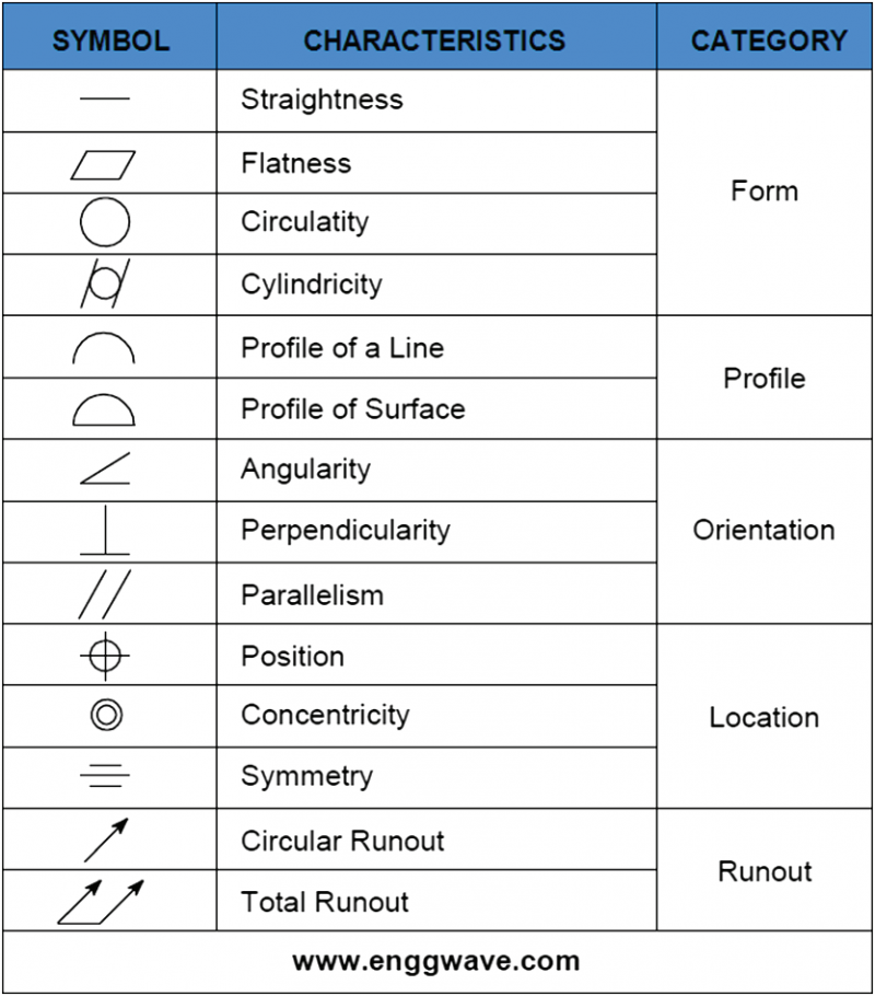
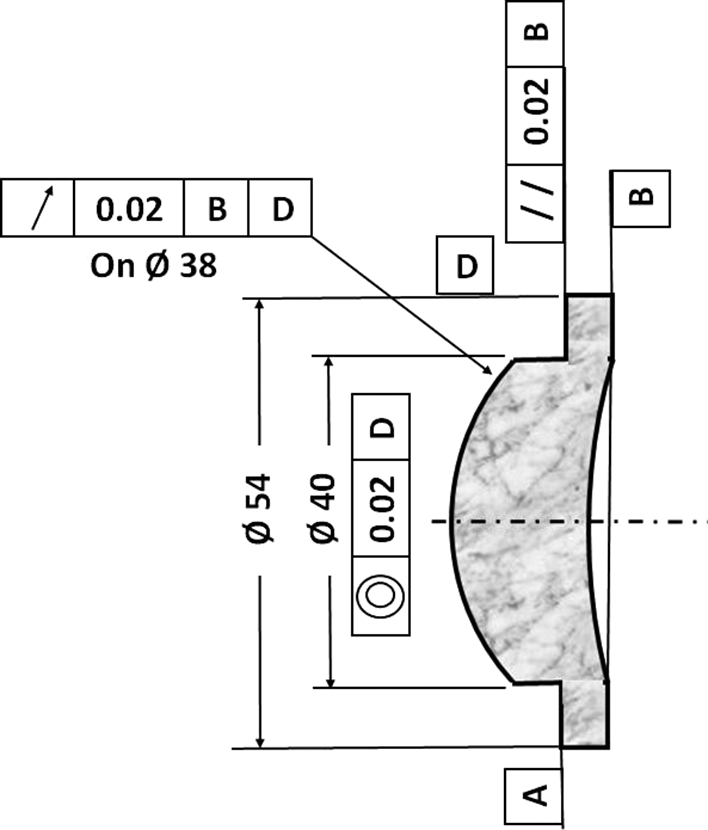
Figure below applies some of these symbols to an example.
This explanation of metrology and GD&T also refers to the field of optics, but due to its additional and special requirements, there was a need to establish additional standards and specifications, i.e., drawings, symbols, tests, and inspections.
Rules of Thumb for Measurement Tools
The following “rules of thumb” are guidelines for selecting a suitable measurement tool that are derived from experience or practice without any formal or scientific basis.
Rule of 10 (10:1): “The Rule of Thumb (for 10:1) is to select a measuring tool that is ten times more accurate than the total tolerance to be measured, or the tool can discriminate to one-tenth of the total part tolerance” (Grifith 2003). For example, if the tolerance of the lens diameter is ±0.02 mm, then the resolution of the measurement inspection tool (e.g., micrometer) should be as small as 0.02/10 mm (0.002 mm).
Rule of 4 (4:1): Like the Rule of 10 but the tolerance is divided by 4. For example, if the tolerance of the sagitta of the concave optical surface is 0.015, then the resolution of the measurement inspection tool (e.g., indicator) should be as small as 0.015/4 mm (0.00375 mm).
Note that in many cases the tools are not available according to the above rules, but, for measurement purposes, these rules of thumb connect the tolerance with the uncertainty (of the measurement and the result). Because the measured results must be certain, always use a tool with a higher resolution than the stated tolerance requirement!