Laser for Scanner
Scanner technology is a third alternative to moving either the machining head or the workpiece; this approach is gaining significance in laser applications. The laser beam is deflected and positioned by one or two galvanometrically moved rotating mirrors. Subsequent focusing is usually effected via an optimized lens system. In certain cases, such as remote welding, the focusing lens may be positioned in front of the scanner head.
A much higher processing speed is usually achieved compared to moving workpiece axes, combined with typically lower investment costs. The limiting factor in scanner technology is the size of the processing field, which depends on the focal distance of the optical system. The focus diameter, too, is a function of the focal distance as well as the beam properties. A suitable optical system is therefore selected in accordance with the desired focus diameter and the size of the processing field.
Laser marking is by far the most popular application of scanner technology. For some years, scanner technology has successfully established itself in the areas of welding, cutting, drilling, and structuring of smaller components as well. The user simply defines the processing geometry of the laser beam, including the respective path parameters, and enters these data in a CAD front end.
The term “dynamic beam technology” is occasionally used to indicate the speed and flexibility of this technique.
Categories of dynamic beam welding encompass fiber-coupled laser beams as well as direct-beam systems. In the case of fiber-coupled systems, the fiber divergence, the size of the steering mirrors, and the focusing optics must be adapted to the welding spot size and the processing field size. In order to minimize the welding spot size and to create a sufficiently large processing field, special bending mirrors with a larger geometric aperture are normally used for this purpose. Consequently, the speed of movement is slower than in laser marking, but it is usually still fast enough to make the laser power the limiting factor. When using solid-state lasers for direct-beam methods, it is necessary to make sure that the thermal lensing of the laser rod (crystal) is sufficiently compensated. To this end, special resonators, ”sweet spot resonators“, are used. Compared to fibercoupled systems, this provides a much better beam quality and thus much smaller welding spot diameters. It should be noted, on the other hand, that these resonators usually have a limited average power and therefore lend themselves to micro welding techniques in particular.
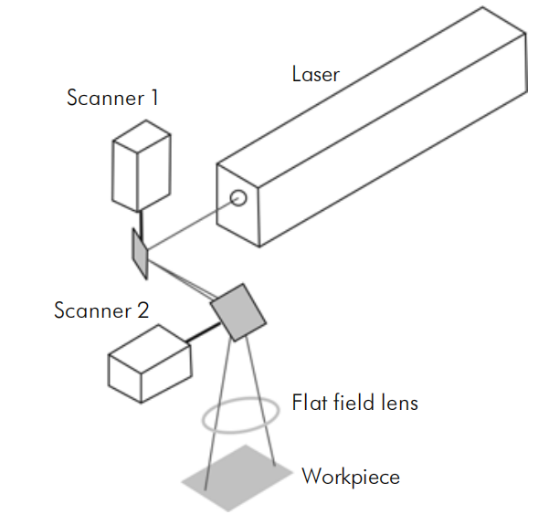
The direct beam technique, along with high-power CO2 lasers, is also used for welding purposes; this is known as a Remote Welding System (RWS). The Remote Welding System is a highspeed system used to create a multitude of laser stitch-welds, combined with very short non-productive welding times, making this technique a primary competitor for resistance spot welding. The speed of beam movement between weld lines, referred to as “rapid move“, is faster than 2 m/sec.
High-performance lasers with a power in excess of 3 kW and high beam quality (< 5 mm x mrad) are needed to obtain an economically viable Remote Welding System. With a 6 kW CO2 Slab laser and a focal distance of more than 1.6 m, this results in a pyramidal working envelope with a base area of 1500 mm x 2400 mm. In addition to welding spots, weld seams with varying welding geometries can be produced, such as stitches, circles, semicircles, crosses, and corrugations.
The laser beam is expanded by a telescope and is guided onto the working area by a transmitting optical system. This optical system is mounted on a linear carriage, where its translational movement defines the position of the focal point along the z-axis. In common with laser marking scanner optics, positioning along the x and y coordinates is effected via a rotating mirror.
![]()
In addition, the mirror along the y-axis may be displaced to enlarge the working area. This system design completely separates clamping technology from welding technology.
Due to the high point-to-point velocity, the Remote Welding System, compared to resistance spot welding with robots, can produce up to ten times more weld lines within a given time period. The possibility of positioning the laser above the welding spot affords a compact system requiring a minimum of floor space.
Dynamic Beam Structuring, Cutting and Drilling
The dynamic movement of the laser beam is limited where it is necessary to use a gas assist for expelling material; this precludes the use of this technique for melt and oxidation cutting.
Due to the high velocity of movement, the scanner technique, however, lends itself excellently to ”sublimation ablation“ (better described as: vapor pressure-induced melt displacement). The ablation depth of a single track is of the order of a few microns, typically between 0.1 and 30 µm. By using these individual tracks (dynamic beam structuring), for instance, layers may be selectively removed (photovoltaic, cable insulation, etc.) or grooves may be introduced to component surfaces (photovoltaic, tribology, etc.).
Dynamic Beam Cutting involves the separation of thicker cross-sections by repeated scanning of the same contour (multi-pass cutting).
In Dynamic Beam Drilling, scanner movements may be used to quickly and flexibly approach positions for individual or percussion drilled holes. On the other hand, the geometry of the hole may be created by mirror movements during percussion drilling (trepan drilling, twist drilling).
Two parameters essentially determine the precision of *dynamic beam* technology: the repeatability of position as well as the temperature drift. The repeatability depends largely on the type of scanner head as well as on the size of the aperture (larger mirrors have a lower speed and higher positioning precision). In order to suppress the temperature drift, the scanners are heated to a constant temperature.
Additional water-cooling is provided for high-precision applications.