How laser can be used for Alignment?
Many modes can exist within a laser cavity.
However, in order for these modes to form, there must be a reflection path between two optical components. For this reflection path to exist the two optical components must be precisely parallel with each other to within fractions of a wavelength of the light being reflected. The best way to determine if two optical surfaces are parallel is to bounce laser beams off of them and to then adjust the relative position of the two optics until the reflected spots overlay upon each other.
Figure here shows a typical configuration for aligning a laser cavity.
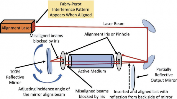
An alignment laser is used as the main tool for this purpose. Typical alignment lasers are helium–neon (HeNe), diode-pumped solid-state lasers, and sometimes other lasers might be used. The alignment laser should be Class 2 or less, so eye safety is not of major concern and it will also help us find where reflections and stray light might go once the higher-power laser is turned on.
The alignment beam is best implemented when bounced off of two highly reflective (100%) mirrors that are adjustable in altitude and azimuth (two axes). These mirrors are used to place the beam through the center of the laser apparatus and active medium.
To more precisely align the system, we place an adjustable iris (or sometimes just a pinhole) with a smaller diameter then the active medium at the entrance and exit of the medium. In order for the alignment beam to make it through the smaller apertures the beam must be more precisely parallel with the axis of the laser-active medium and optical pathway. Alignment of the back reflector is typically done first. As the mirror is adjusted so that the reflected beam passes back through the irises and then back onto the exit aperture of the alignment laser, a set of interference rings will form on the face of the alignment laser. These rings will appear because the back reflector of the laser being aligned and the output coupler of the alignment laser form a Fabry–Perot interferometer once alignment has been accomplished.
Once the back reflector is aligned the output coupler is inserted into place.
The mirror is adjusted until the reflection from the outside (back surface) of the output coupler is incident back onto the alignment laser-exit aperture.
In some cases, the light from the back reflector is brighter than from the output coupler making it difficult to see if the output coupler is aligned or not. Placing an index card in front of the back reflector during alignment of the output coupler is typically a good practice. This will block the reflection from the back reflector and therefore the interference rings will vanish.
Once new interference rings appear from the cavity formed between the output coupler of the laser and the output coupler of the alignment laser the card can be removed and the laser is then aligned. Also note, that before the higher-power laser is turned on the path to the alignment mirrors must be blocked, averted, or one of the mirrors must be removed or the alignment laser might be damaged.
Figure here shows a configuration for aligning a more complex optical cavity.
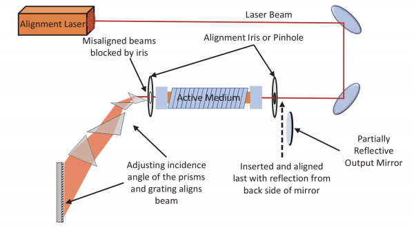
The approach is very similar as described above with the added difficulty of aligning dispersive elements such as prisms and gratings. But in general, the approach is to create reflective pathways from the final reflective optic (in this case a grating) back through the cavity and onto the face of the alignment laser.